Copyright ©2018, 2020, 2021, ASSA ABLOY Access and Egress Hardware Group, Inc. All rights reserved. Reproduction in
whole or in part without the express written permission of ASSA ABLOY Access and Egress Hardware Group, Inc. is prohibited.
For technical support contact Yale
®
at 800.438.1951 x5033 or support@yalelocks.com
12
Delayed Egress
Installation Instructions
7100, 7200 Series Exit Device
8094700162000 04/21
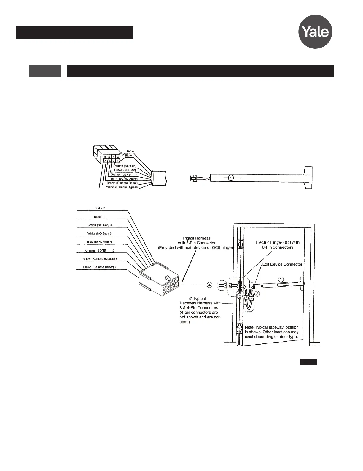
9 Installing Delayed Egress Exit Device
Refer to Figure 6 for delayed egress exit device installation wiring.
NOTE: For ElectroLynx Hinge Connector System: Follow Section 6 wiring instructions.
For non-ElectroLynx door:
Remove connector at end of exit device and connect to incoming wires from power source using wire
nuts, butt splices, etc. See Section 14 for hole locations and sizes.
Red +2
Black - 1
Green (NC) Sec 4
White (NO) Sec 3
Blue (NO/NC Alarm) 6
Orange (EGND) 5
Yellow (Remote Bypass) 8
Brown (Remote Reset) 7
Pigtail Harness with 8-Pin
Connector (Provided with exit
device or QC8 hinge)
Electric Hinge - QC8 with
8-Pin Connectors
Exit Device
Connector
3” Typical Raceway Harness with 8 &
4-Pin Connectors. (4-pin connectors
are not shown and are not used).
Note: Typical raceway location is shown. Other locations
may exist depending on door type.
ElectroLynx system has wires with
connectors that snap together.
Locking mechanism
Male plug (8 circuit)
Female
receptacle
(8 circuit)
Figure 6
 Loading...