Do you have a question about the Yale Assure Lever YRL236 and is the answer not in the manual?
Lists all parts and tools provided for installation, including screws and batteries.
Instructions to download the BILT app for step-by-step installation guides and product registration.
Details standard tools like a Phillips head screwdriver required for installation.
Lists tools needed specifically for new doors or adjusting existing door preparations, like drills and chisels.
Specifies required backset dimensions (2-3/8" or 2-3/4") and bore diameter (2-1/8").
Confirms the acceptable door thickness range (1-3/8" or 1-3/4") for proper lock fit.
Explains how to identify left-hand, right-hand, and reverse door handing based on swing direction.
Illustrates the correct alignment of the latchbolt curve with the strike plate for proper function.
Provides instructions and diagrams for drilling the necessary holes in the door for the lock mechanism and spindle.
Shows how to prepare the door frame for the strike plate installation, including depth and diameter.
Details how to install the latch mechanism and adjust it based on the door's backset (60mm or 70mm).
Shows the correct placement and attachment of the strike plate to the door frame.
Emphasizes the importance of the "TOP" mark and vertical tailpiece orientation for correct installation.
Illustrates how to connect the exterior push button unit to the latch mechanism.
Guides the user on how to attach the interior mounting plate to the door using screws.
Shows the interior view with the mounting plate installed, ready for battery insertion.
Details how to securely connect the cable assembly from the exterior unit to the interior mounting plate.
Provides guidance on properly routing the cable using provided hooks to avoid interference.
Shows how to align and attach the main interior lock housing onto the mounting plate.
Demonstrates the final seating of the interior lock unit, indicated by a "Click".
Illustrates inserting the key-free cylinder into the exterior of the lock assembly.
Advises on the correct orientation of the cylinder, ensuring the bar faces away from the latch.
Shows how to slide the exterior lever onto the spindle and lock mechanism.
Warns to press the pin while installing the lever to prevent damage to the lock.
Demonstrates fitting the interior lever onto the spindle on the inside of the door.
Reminds users to press the pin while installing the lever to avoid damaging the lock.
Guides on testing the thumbturn and levers in both locked and unlocked positions with the door open.
Advises to check installation from Step 3 if mechanical operation fails.
Explains how to install an optional Smart Module, noting batteries should not be installed first.
States that if a Smart Module is included, separate instructions are provided.
Shows the placement of AA alkaline batteries into the interior lock unit.
Illustrates replacing the battery cover to complete the physical installation.
States that a Master Entry Code must be created first for programming and lock usage.
Instructs to test the push button operation with the door open after creating the Master Code.
Provides a step-by-step guide to reset the lock to its original factory settings.
Notes that creating a Master Entry Code is mandatory after a factory reset before other programming.
Details the default settings for various lock features like Audio Mode, Re-lock Time, and Lockout Mode.
Provides a note to installers and consumers regarding lockout situations and the recommendation for alternative entry points.
Addresses issues with tailpiece/spindle mating and thumbturn rotation.
Covers problems like jam alarms, no sound, noise during operation, and locking pin retraction.
States that a Master Entry Code must be created before any other programming can be done.
Informs about the maximum number of user codes that can be programmed with or without a Smart Module.
Shows how to start the process by pressing the Yale button and the checkmark.
Guides on entering the 4-8 digit Master Entry Code and confirming it.
Details the steps to add new user codes after the Master Code is set.
Explains how to exit the user code programming mode by pressing the checkmark.
Shows how to enter a valid code and press the checkmark to unlock the door.
Provides a blank chart for users to record Master and User Entry Codes.
Defines All Code Lockout Mode and Audio Mode settings and their functions.
Explains Automatic Re-lock, Inside Indicator Light, and Low Battery warnings and their behavior.
Defines Master Entry Code, Smart Module Setting, One Touch Locking, Shutdown Time, Tamper Alert, User Entry Code, and Wrong Code Entry Limit.
Outlines the process of entering the Master Code and menu digits to access features.
Details how to set the Master PIN and register/delete User PIN codes.
Explains how to adjust Automatic Re-lock, Inside Indicator Light, and One Touch Locking.
Covers setting Audio Mode and All Code Lockout Mode.
Addresses symptoms like the lock not responding or not unlocking after code entry.
Provides solutions for entry codes not registering or issues with code acceptance.
Helps resolve problems with lock sounds, intermittent flashes, and incorrect code responses.
Details FCC rules for Class B digital devices regarding interference.
Outlines Canadian compliance requirements for digital apparatus.
Provides contact info and copyright details.
Instructions to remove batteries before installing or removing the Z-Wave module.
Steps to enroll and unenroll the Z-Wave module into/from a Z-Wave network.
Details FCC rules regarding radio frequency exposure limits for the device.
Explains Industry Canada's requirements for RF exposure limits and antenna gain.
States the conditions for device operation as per FCC and Industry Canada regulations.
Instructions to remove batteries before installing or removing the ZigBee module.
Steps to enroll and unenroll the ZigBee module into/from a ZigBee network.
Reiteration of FCC and IC compliance, including warnings about modifications.
Provides company overview, trademarks, and mission statements.
| Lock Type | Lever |
|---|---|
| Keypad | Yes |
| Bluetooth | Yes |
| Battery Life | Up to 1 year |
| Battery | 4 AA batteries |
| Bump Proof | Yes |
| Auto-Lock | Yes |
| Remote Access | Yes |
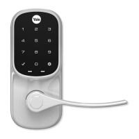
| Finish | Satin Nickel |
| User Codes | Up to 25 |
| Warranty | 1-year electronic |
| Backset | 2-3/8" or 2-3/4" |
| Door Thickness | 1-3/8" to 1-3/4" |
| Keyway | No Keyway |
| Connectivity | Bluetooth, Wi-Fi |