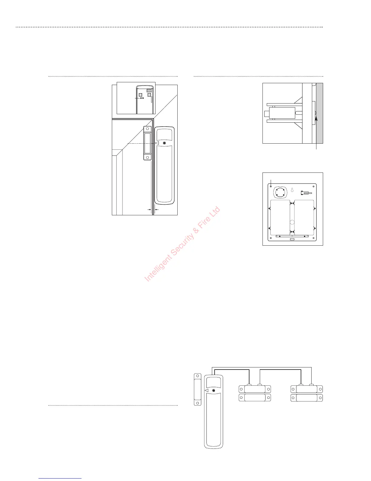
Door/Window contact
1 Ensure the jumper
switch is in the test
‘On’ position.
• In this position the
indicator light will
illuminate every time
the door contact is
operated.
2 Fit as described
above under
Alternative mounting
methods, mounting
the detector base on
the frame and
aligning the magnet
by the arrow as
shown.
• The magnet should
not be more than
8mm from the
detector when the door is closed.
• Ensure the tamper switch spring is positioned
so that it makes contact with the mounting
surface through the tamper switch aperture.
• If the door contact cannot be mounted on the
doorframe, use the HSA3090 multiple
door/window contact accessory kit with a
length of wire to mount the door contact
remotely.
• When fitting to a window, fix the magnet to the
moving part and the detector to the frame.
3 Fix the detector on its base and secure with
screw. Test it by opening and closing the door
or window. The light will flash when an open
condition is detected.
4 Remove the detector, put the jumper switch in
the normal ‘Off’ position. Screw the detector
back onto its base.
• When the jumper is in the normal Off position
the indicator light will normally be off. It will
only light if there is a problem, either a low
battery or a tamper condition.
• Ensure the jumper is in the normal Off position
when testing is finished, otherwise low battery
and tamper conditions will not be shown.
Adding door/window contacts
More than one window and door can be protected
by a door contact using the HSA3090 multiple
door/window contact accessory kit. The contacts
must be wired to the auxiliary switch terminal
block as shown.
Siren
WARNING
The siren is
extremely loud!
The tamper switch
plunger protrudes
through the back of the
unit, so that if the siren
is pulled from the wall
the alarm is activated.
Ensure it is fully
depressed when the siren
is mounted. If there is a
gap, pack with a suitable
spacing material.
1 Find suitable location,
as previously
described in
section 3.
2 Disable the system
tampers by pressing
and holding the Home
and Arm buttons
simultaneously until
the siren confirms
with a beep (approx 5 seconds).
3 Using the large screws provided, mount on wall
through the base plate mounting holes shown.
4 Fix the siren cover with the securing screw.
5 Put system into normal tamper detection mode
by pressing and holding the keyfob Arm and
Panic buttons simultaneously until the siren
confirms with a beep (approx 5 seconds).
6 Test by arming and disarming with the keyfob.
If 5 pips sound the tamper is not correctly set.
Installation is complete.
11
Tamper switch plunger
must be pressed in fully by
wall surface
Jumper
switch
Door/
Window
Frame
Align
8mm (max)
Fixing holes x 4

 Loading...