10
Mounting and testing
Before mounting detectors ensure that the system tamper is disabled as described
in section 2, point 4.
4
Testing the radio performance
Before permanently installing the system,
check that the siren will receive the system radio
transmissions by doing a simple radio range test.
1 Ensure that the system tamper is disabled.
2 Mount the siren temporarily in the location you
have chosen.
• Use either a masonry nail or single screw in the
siren base keyhole to temporarily fix in place.
3 Hold the device in the desired location and
activate, check that the siren responds.
• The PIR and door contact can be tested by
pressing the learn/test button.
• The keypad can be tested by arming and
disarming the system.
• The smoke detector is tested by pressing the
button until the siren responds (approx 10
seconds).
4 When you are satisfied that the devices work in
their chosen locations, proceed with the
installation as described below.
• If the device does not respond, the location
may be out of radio range, try alternative
locations until reliable radio contact is obtained.
Alternative mounting methods
Yale provide two methods of mounting. Choose
either the self adhesive pads or the screws and
wall plugs supplied.
Self adhesive installation
for door/window
contact and smoke detector accessory
Clean the surface with a suitable degreaser.
Remove the protective covering from one side of
the double sided adhesive pad and firmly apply to
the back of the device. Next remove the other
cover and firmly press the item onto the desired
location.
• Do not use the adhesive pad method of
installation on a surface with peeling or cracked
paint, or on a rough surface.
Screw mounting
Remove the front of the device, and, if
necessary, break through the appropriate knockout
(where the plastic is thinner).
Using the holes as a template, drill holes in the
surface and insert the wall plugs if fixing into
plaster or brick.
PIR movement detector
The PIR has a built-in sleep timer to save
battery power. If there is no movement in front of
the PIR for 1 minute, the PIR will become ‘ready
to signal’ and movement will now be reported.
The PIR will sleep for 1 minute after. Any
movement detected in sleep time will not be
reported and will extend the sleep period by 1
minute. This feature is designed to conserve
battery life.
Ensure the test/normal mode jumper switch is
in the test ‘On’ position. This reduces the sleep
time to a few seconds and enables the LED to
flash every time movement is
detected.
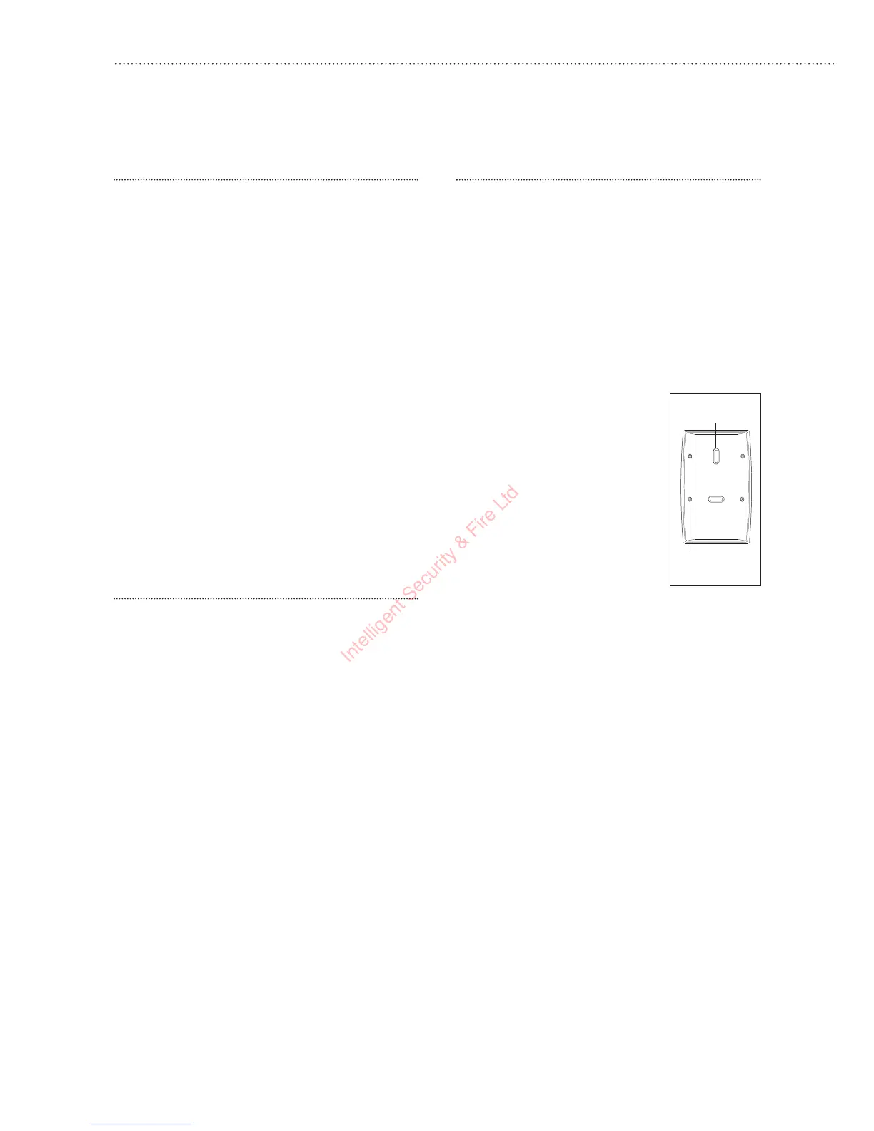
1 Screw the rear case to the wall
using two of the knockouts
shown, as described above
under Alternative mounting
methods. The case has angled
back edges for neat corner
mounting. Screw the PIR front
on.
2 Walk around the protected area
noting when the LED flashes
and check that the detection
coverage is adequate.
• Remember to wait a few seconds after the PIR
has detected movement.
• Do not try to test the detection pattern by
walking straight up to, or away from the
detector.
3 When you are satisfied with the detection
coverage, remove the PIR, place the jumper in
the normal ‘Off’ parked position and screw the
PIR back on to its case.
• With the jumper in the normal position the LED
will not normally light unless there is a problem,
either a low battery or a tamper condition. In
the event of a low battery, replace the
exhausted batteries with fresh alkaline
replacements.
• Do not position a PIR to look directly at a door
protected by a door contact, this could cause
the door contact and PIR radio signals to be
transmitted at the same instant when entering,
cancelling each other out.
• Ensure the jumper is in the normal Off position
when testing is finished, otherwise low battery
and tamper conditions will not be shown.
Corner fixing
holes x 4
Surface fixing
holes x 2