Do you have a question about the Yale SLE 3 and is the answer not in the manual?
Explains the purpose of these operating instructions as safety manuals for the SLE 3 electronic control unit.
Lists the subjects covered in the operating instructions, including safety, product description, installation, and maintenance.
Refers the user to the Technical Data chapter for information on approvals and test marks.
States that compliance with operating instructions is fundamental for safe operation and warranty.
Explains safety symbols (DANGER, WARNING, CAUTION, ATTENTION) and specific symbols for electrical voltage, suspended load, hand injuries, and recommendations.
Identifies electrically skilled persons and competent persons as the target audience for installation, commissioning, and maintenance.
Outlines prerequisites for warranty claims, emphasizing compliance with operating instructions.
Warns against using the device for purposes other than those stated in the manual.
Highlights that the SLE 3 achieves safety function only when programmed correctly and requires documented commissioning.
Lists relevant directives (Machinery, EMC) and European standards (IEC/EN 60204-32, EN 14492-2, ISO/EN 13849-1) for the SLE 3.
Specifies that the SLE 3 is for manual single hoists, industrial installations, and acts as a safety device for overload protection.
Provides guidelines for electrical installation, including switch cabinet protection (IP54), wiring standards, shielded sensor cables, and fuse limits.
Emphasizes the importance of a protective earth connection for preventing electric shock and ensuring proper function.
Details residual risks such as unexpected start-up, direct contact with power supply, and failure of downstream power elements.
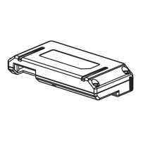
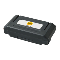
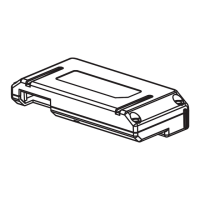
Describes the SLE 3 as an electronic control unit for hoists with safety-related overload cut-off and other monitoring functions.
Explains that the SLE 3 processes signals from passive DMS load sensors and stresses using only manufacturer-approved sensors.
Illustrates the front panel of the SLE 3, labeling connection terminals, DIP switches, and signaling LEDs.
Presents a block diagram showing the internal connections, inputs, outputs, and functional modules of the SLE 3.
Provides a detailed schematic circuit diagram illustrating the electrical connections and signal flow within the SLE 3.
Details the overload cut-off function, its design according to ISO 13849-1, and operational cases.
Describes how the SLE 3 detects and processes sensor errors (broken cable, short circuit, differential error) and their impact.
Explains the function of safety inputs (S↑, S↓, S↑↑) and their relation to output actuation and safety category.
Details the function of safety outputs (K↑, K↑↑, K↓, K↓↓) and their actuation by internal safe circuits.
Explains motor management functions, including off-times for lifting/lowering, and factors affecting them.
Presents a table showing the relationship between motor types, switch settings (S1, S3), and motor management times (ts, tf, tr, ta, tb).
Describes the function of the integrated operating time counter that logs hoist motor operation hours.
Explains temperature monitoring via thermistors (input 91, 92) and the resulting error indications and blocked movements.
Details the parameterization and function of signaling relays ('err', 'option') for outputting error messages.
Provides the physical dimensions of the SLE 3 device (100 x 110 x 75 mm).
Describes mounting options: snap-on attachment to a 35 mm top hat rail and screw attachment.
Refers the user to the 'Technical data' section for details on cable connections.
Advises installing sensor cables and power lines separately and adhering to maximum cable lengths.
Specifies that the device must be mounted in a switch cabinet with at least IP 54 protection.
Outlines the importance of qualified personnel for commissioning and testing, and details types of tests (acceptance, regular).
Explains how to change the cut-off point using the testing bay function, emphasizing qualified personnel and permissible ranges.
Describes the testing bay function for setting overload cut-off points and warns of dangers if errors occur.
Provides a step-by-step guide for activating the testing bay function, including switch settings and LED indications.
Explains the crane test for increasing the overload cut-off point and its activation/deactivation by qualified personnel.
Details the procedure for activating the crane test function, including stationary state, load conditions, and switch settings.
Describes methods for deactivating the crane test function, such as restarting the device or pressing button S5.
Stresses the importance of documenting cut-off point changes in the device cover, a table, and the crane logbook for warranty.
Provides instructions for replacing the device or sensor, emphasizing restoration of original installation state and re-commissioning.
Recommends checking screw terminals for tightness annually as part of maintenance.
States that the SLE 3 has no wear parts and defective devices must be replaced with equivalent ones.
Explains internal tests upon power-on and the conditions for the SLE 3 to be ready for operation (only 'pwr' LED on).
Details error states, their causes (sensor error, overload, overheating, internal error), consequences (blocked movements), and correction methods.
Describes warning messages (crane test active, activation error, overheating, overload, testing bay) and their impact on travel motion.
States operator responsibility for decommissioning, disposal of electronic scrap according to environmental laws, and notes the absence of batteries.
Lists voltage variants (AC, DC), voltage tolerance, power consumption, and fuse protection for the SLE 3.
Details galvanic isolation and signal level thresholds for inactive and active states.
Specifies utilization categories and current ratings for control and signaling relays per standards.
Provides technical details for the load sensor, including type, supply voltage, signal input, measurement range, and error tolerance.
Lists resistance values for PTC inputs related to motor temperature monitoring.
Specifies insulation strength, clearances, creepage distances, pollution degree, and overvoltage categories.
Lists specifications for impact, vibration resistance, and EMC immunity/emission standards.
Specifies the operating temperature range (-20 °C to +55/70 °C) and storage temperature range (-40 °C to +80 °C).
Details dimensions, protection rating, connection terminal specifications, attachment, and weight.
Lists maximum cable lengths for digital control signals, temperature inputs, and sensor inputs.
Lists safety parameters (PL, PFH, MTTFd, DC, Category, Response time) for the SLE 3 and its components.
Explains that type designation, hardware, and software versions are found on the rating plate.
Illustrates the structure of the type designation for the SLE 3, including parameters like temperature range and hardware version.
Provides a table for documenting changes to device settings, including reason for change and signatures.
Blank page for user notes.
| Brand | Yale |
|---|---|
| Model | SLE 3 |
| Category | Control Unit |
| Language | English |