CRANKSHAFT
5-63
EAS24390
CHECKING THE CYLINDER AND PISTON
1. Check:
• Piston wall
• Cylinder wall
Vertical scratches → Replace the cylinder,
and replace the piston and piston rings as
a set.
2. Measure:
• Piston-to-cylinder clearance
▼▼▼▼▼▼▼▼▼▼▼▼▼▼▼▼▼▼▼▼▼▼▼▼▼▼▼▼▼▼
a. Measure cylinder bore “C” with the cylinder
bore gauge.
NOTE:
Measure cylinder bore “C” by taking side-to-
side and front-to-back measurements of the
cylinder. Then, find the average of the mea-
surements.
b. If out of specification, replace the cylinder,
and replace the piston and piston rings as
a set.
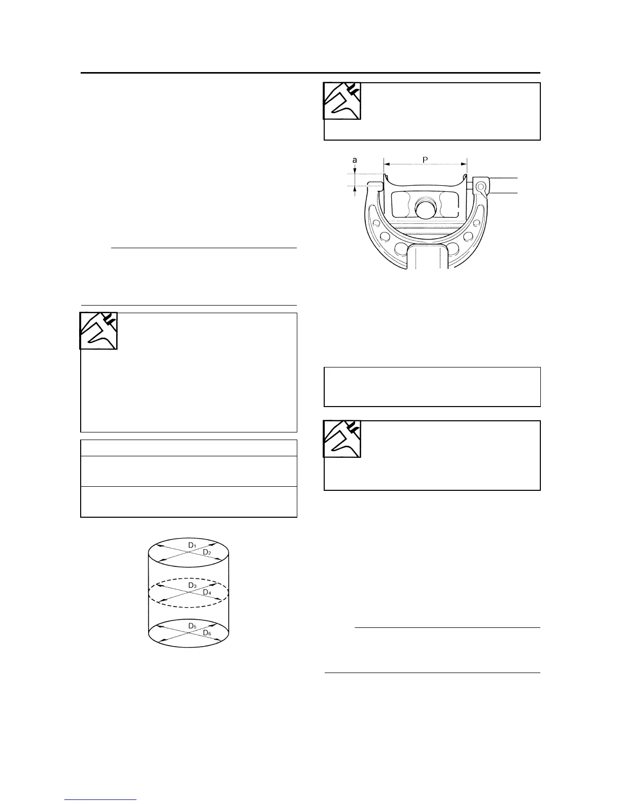
c. Measure piston skirt diameter “P” with the
micrometer.
d. If out of specification, replace the piston
and piston rings as a set.
e. Calculate the piston-to-cylinder clearance
with the following formula.
f. If out of specification, replace the cylinder,
and the piston and piston rings as a set.
▲▲▲▲▲▲▲▲▲▲▲▲▲▲▲▲▲▲▲▲▲▲▲▲▲▲▲▲▲▲
EAS24430
CHECKING THE PISTON RINGS
1. Measure:
• Piston ring side clearance
Out of specification → Replace the piston
and piston rings as a set.
NOTE:
Before measuring the piston ring side clear-
ance, eliminate any carbon deposits from the
piston ring grooves and piston rings.
Bore
65.500–65.510 mm (2.5787–
2.5791 in)
Wear limit
65.56 mm (2.5811 in)
Taper limit
0.050 mm (0.0020 in)
Out of round limit
0.050 mm (0.0020 in)
“C” = maximum of D
1
–D
6
“T” = maximum of D
1
or D
2
- maximum of D
5
or D
6
“R” = maximum of D
1
, D
3
or D
5
- minimum of
D
2
, D
4
or D
6
Piston size “P”
Standard
65.475–65.490 mm (2.5778–
2.5783 in)
a. 4 mm (0.16 in) from the bottom edge of the
piston
• Piston-to-cylinder clearance =
Cylinder bore “C” -
Piston skirt diameter “P”
Piston-to-cylinder clearance
0.010–0.035 mm (0.0004–
0.0014 in)
Limit
0.05 mm (0.0020 in)
 Loading...