Do you have a question about the Yamaha A-1 and is the answer not in the manual?
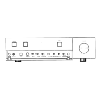
Controls the main power supply to the amplifier.
Enables or disables the connected speaker system.
Prioritizes direct signal path from disc playback.
Adjusts the overall sound volume level.
Provides access to less frequently used controls via a removable panel.
Connection point for headphones, allowing private listening.
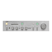
Modifies the low-frequency response of the audio signal.
Modifies the high-frequency response of the audio signal.
Enables or disables the BASS and TREBLE tone control circuits.
Changes audio output between stereo and monaural modes.
Allows monitoring of playback signals from a connected tape deck.
Selects the desired audio input source for playback.
Matches the amplifier's input to MM or MC type phono cartridges.
Instructions for connecting speaker systems, including polarity and terminal connection.
Guide for connecting MM and MC cartridges, and cartridge load plugs.
Steps for high-fidelity playback using the direct signal path.
Procedure for adjusting sound with tone controls when DISC switch is OFF.
Instructions for connecting an AM/FM tuner to the A-1's TUNER input jacks.
Guide for connecting other audio sources like mic mixer amplifiers or tape players.
How to connect a tape recorder to the A-1 via TAPE PB and REC OUT terminals.
Procedures for playing and recording audio using a tape deck.
Instructions for copying audio between two tape decks using the A-1.
Guidance on connecting and using headphones with the A-1's PHONES terminal.
Explains the direct coupling function of the DISC switch for record playback.
Details how input impedance affects MM cartridges and how to use load plugs.
Overview of the A-1's circuit design, including DISC ON/OFF configurations.
Technical description of the equalizer amplifier's components and performance.
Details on the A-1's main amplifier design, sensitivity, and characteristics.
Information about the built-in MC head amplifier for direct MC cartridge sound.
Explanation of the tone control circuit, including its subsonic filter function.
Description of the power supply circuit featuring dual transformers and large capacitors.
Discussion of enhancements in overall performance and noise reduction.
Definition and explanation of Noise-Distortion Clearance Range (N.D.C.R.).
Graph showing distortion levels relative to output power.
Graph illustrating Intermodulation distortion versus output power.
Graph showing noise levels and volume attenuation from PHONO to SP OUT.
Graph detailing total harmonic distortion across different frequencies for TUNER input.
Graph showing RIAA equalization curve deviation for PHONO input.
Graph of total harmonic distortion versus output power for TUNER input.
Detailed specifications for output power, total harmonic distortion, and IM distortion.
Specifications for input sensitivity, impedance, maximum input levels, and frequency response.
Specifications for tone control ranges, output levels/impedances, and signal-to-noise ratios.
Specifications for channel separation, N.D.C.R., headphone output, and AC outlets.
Details on power requirements, physical dimensions, and weight.
Solutions for problems related to power supply and absence of reproduced sound.
Remedies for low sound with MC cartridges and non-functional tone controls.
Solutions for no sound from speakers, sudden sound loss, and unstable sound image.