A5000/A4000
7
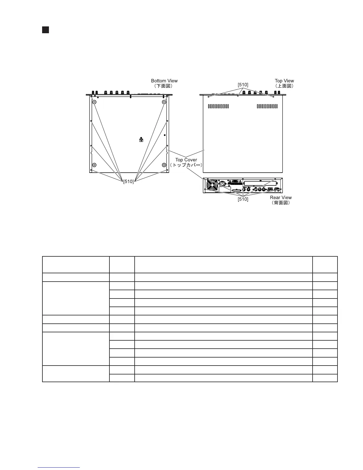
1. Top Cover
1-1 Remove the sixteen (16) screws marked [510] and slide the Top Cover to the back side. The top cover can be then
removed.
DISASSEMBLY PROCEDURE
2. Circuit Boards and Unit
After removing the top cover, remove the following screws. Each circuit board can then be removed.
Note: *1 Before removing the DM, remove the HDD Ass'y.
*2 Two for A4000.
*3 Before removing the FDD Ass'y and the PS cover Ass'y, remove the Push Rod.
*4 Before removing the PS and Fan Ass’y, remove the PS cover Ass’y.
(Fig.1)
Circuit Boards and Unit Ref.No. Screw Qty
HDD Bracket
DM*
1
FDD Bracket*
3
PS Cover Ass'y
PS*
4
Fan Ass’y*
4
[220]
[120]
[130]
[140]
[150]
[190]
[90]
[100]
[30]
[50]
[60]
[L40]
[L50]
Bind Head Tapping Screw-B 3.0X6 MFZN2Y (EP600130) (fig.2)
Bind Head Tapping Screw-B 3.0X6 MFZN2Y (EP600130) (fig.3)
Bonding Head Screw-B 3.0X10 MFZN2BL (VQ049800)(fig.3)
Bind Head Tapping Screw-P 3.0X8 MFZN2BL (EP630220) (fig.3)
Pan Head Screw 2.5X6 SUS (VV342700)(fig.3)
Bind Head Tapping Screw-B 3.0X6 MFZN2Y (EP600130) (fig.2)
Bonding Head Screw-B 3.0X10 MFZN2BL (VQ049800)(fig.2)
Bind Head Tapping Screw-B 4.0X8 MFZN2BL (EG340190) (fig.2)
Bind Head Tapping Screw-B 3.0X6 MFZN2Y (EP600130) (fig.3)
Bind Head Tapping Screw-P 3.0X8 MFZN2BL (EP630220) (fig.2)
Bind Head Tapping Screw-B 4.0X8 MFZN2BL (EG340190) (fig.3)
Flat Head Screw 3.0X25 MFN133 (V4814400) (fig.3)
Hexagonal Nut 3.0 MFZN2Y (VA211900) (fig.3)
4
13
2
4(2)*
2
2
4
3
2
7
2
1
4
4