A5000/A4000
9
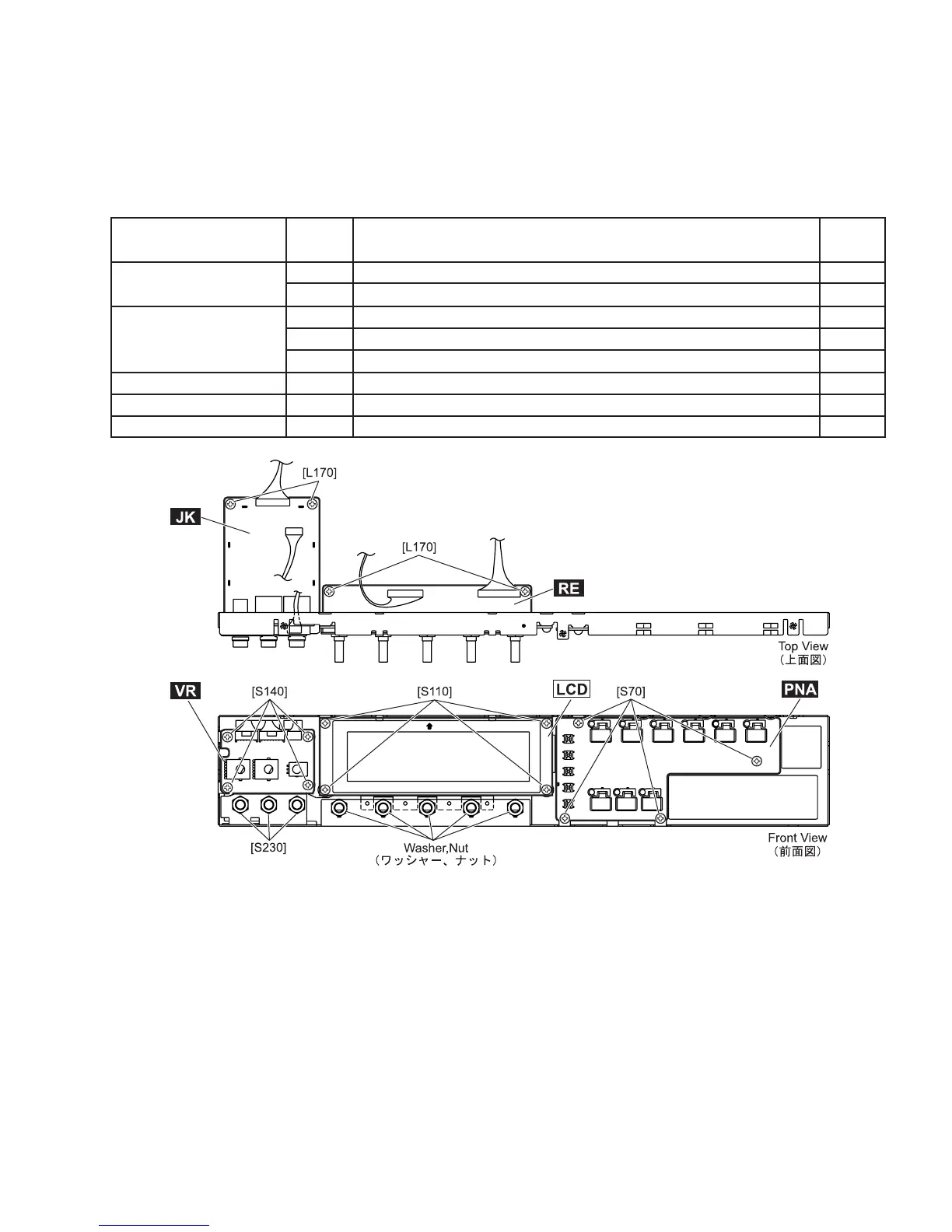
4. Circuit Boards and Unit
After removing the front panel, remove the following screws. Each circuit board can then be removed.(Fig.5)
(Fig.5)
Ref.No. Screw Qty
JK
RE
VR
PNA
LCD
[S230]
[L170]
-
-
[L170]
[S140]
[S70]
[S110]
Hexagonal Nut 14X2 M12 (ES200210)
Bind Head Tapping-B 3.0X6 MFZN2Y (EP600130)
Washer
Nut
Bind Head Tapping-B 3.0X6 MFZN2Y (EP600130)
Bind Head Tapping-B 3.0X6 MFZN2Y (EP600130)
Cup Tapping Screw-B 3.0X6 MFZN2Y (V2644100)
Bind Head Tapping-B 3.0X6 MFZN2Y (EP600130)
3
2
5
5
2
4
4
4
Circuit Boards and Unit