Do you have a question about the Yamaha CR-800 and is the answer not in the manual?
Describes the multiplex demodulator with transistor feedback switching circuit.
Explains the operation of the muting circuit based on signal conditions.
Details power output, distortion, sensitivity, and frequency response for audio.
Lists FM/AM tuning ranges, sensitivity, selectivity, and distortion.
Covers semiconductors, power source, consumption, dimensions, and weight.
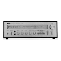
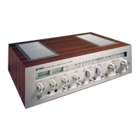
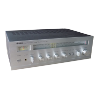
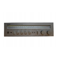
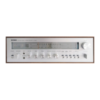
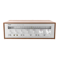
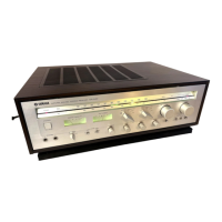
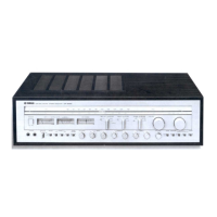
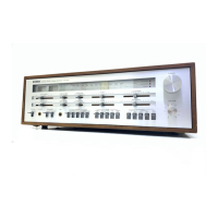
Identifies all controls and indicators on the front panel.
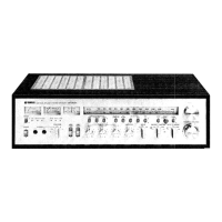
Details input/output terminals on the rear panel for North American models.
Details input/output terminals on the rear panel for European models.
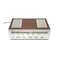
Labels major components visible from the top internal view.
Labels major components visible from the bottom internal view.
Step-by-step guide to removing the front panel assembly.
Instructions for safely removing the main cabinet cover.
Procedure for lowering and removing the main sub chassis unit.
Steps to detach and remove the rear panel assembly.
Guides for removing tuner, AM tuner, main amp, pre-amp, function, power boards.
Guides for removing tuning meter, signal meter, and dial mechanism.
Introduces the FM tuning and adjustment procedures.
Details the steps for adjusting the FM Intermediate Frequency circuit.
Covers FM Multiplex, discriminator balance, tuning point, and IF tuning.
Procedures for aligning the tuner across different frequency bands.
Details the steps for adjusting the AM Intermediate Frequency circuit.
Procedures for aligning the AM tuner across different frequencies.
Procedure for setting the midpoint voltage of the main amplifier.
Procedure for setting the idling current for the main amplifier.
Layouts for the main tuner and AM tuner circuit boards.
Diagrams for 8P/6P pin jack, function, and EQ amp circuit boards.
Layouts for main amp, coupler, pre-amp, and power circuit boards.
Diagrams for LED and DIN connector circuit boards.
Provides a high-level overview of the receiver's circuit blocks.
Lists expected voltage values for transistors under different tuning conditions.
Details component differences in power, antenna, speaker, and tuner sections by region.
Identifies parts by number on front and back panel diagrams.
Lists specific part numbers, descriptions, and remarks for components.
| Power Output | 45 watts per channel into 8Ω (stereo) |
|---|---|
| Input Sensitivity | 2.5mV (MM), 150mV (line) |
| Speaker Load Impedance | 4Ω to 16Ω |
| Frequency Response | 20Hz to 20kHz |
| Total Harmonic Distortion | 0.1% |
| Tuning Range | FM: 88 to 108 MHz |
| Damping Factor | 40 |
| Output | 150mV (line) |