Do you have a question about the Yamaha CR-600 and is the answer not in the manual?
Explanation of the FM muting circuit operation and its components.
Description of the Auto Touch AFC Off circuit and its functionality.
Details on dynamic and continuous RMS power output for the audio section.
Specifications for total harmonic distortion, intermodulation distortion, and hum/noise.
Details on input sensitivity, impedance, and output levels for the audio section.
Technical specifications for the FM and AM tuner sections.
Information on semiconductors, power source, consumption, dimensions, and weight.
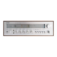
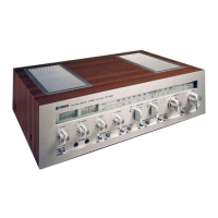
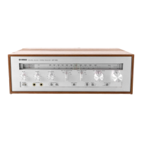
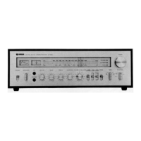
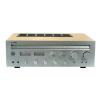
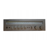
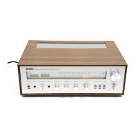
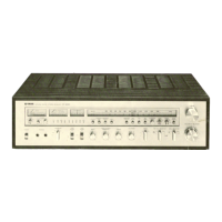
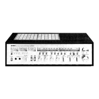
Identification and labeling of controls and indicators on the front panel.
Identification of connectors and terminals on the general model rear panel.
Identification of connectors and terminals on the European model rear panel.
Diagram showing the layout of major internal components from the top view.
Diagram showing the layout of major internal components from the bottom view.
Covers initial disassembly steps: preparation, cabinet, and front panel removal.
Details on removing the sub chassis unit and rear panel circuit board.
Procedures for removing various circuit boards like pre-amp, function, and tuner.
Procedures for adjusting FM IF, AM IF, FM-MPX, FM tracking, and AM tracking.
Steps for adjusting the midpoint voltage and idling current of the main amplifier.
Diagram showing component placement and connections for the tuner circuit board.
Diagrams for EQ, Pre-Amp, and Main Amplifier circuit boards.
Diagrams for Power, Function, Coupler, and other control circuit boards.
| Frequency Response | 20 Hz to 20 kHz |
|---|---|
| Tuning Range | FM, MW |
| Damping Factor | 40 |
| Input Sensitivity | 2.5 mV (MM), 150 mV (line) |
| Output | 150 mV (line) |
| Speaker Load Impedance | 4Ω to 16Ω |
| Signal to Noise Ratio | 90dB (line) |
| Power Output | 30 watts per channel into 8Ω (stereo) |