Do you have a question about the Yamaha CR-400 and is the answer not in the manual?
Details integrated circuits like TA-7122p, LA-3311, and LA-1111.
Information on CF-10M-12 and CF-10H-12 ceramic filters, including specifications.
Details on TLR-102 LED, including maximum ratings and characteristics.
Covers power output, input sensitivity, impedance, tone controls, and bandwidth.
Details semiconductors, power source, consumption, dimensions, and weight.
FM and AM tuning range, sensitivity, rejection, distortion, and frequency response.
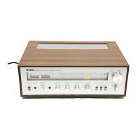
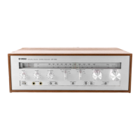
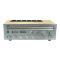
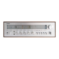
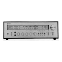
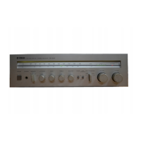
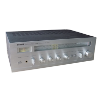
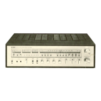
Identifies controls and indicators on the front panel with numbered labels.
Identifies rear panel connectors and terminals for North American models.
Identifies rear panel connectors and terminals for European models.
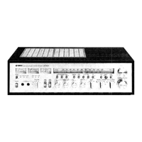
Shows the layout of major internal components from the top.
Shows the layout of major internal components from the bottom.
Step-by-step guide to remove the unit's cabinet.
Instructions for removing the front panel and associated controls.
Procedures for safely removing the meter assembly.
Steps to remove the preamp circuit board and related components.
Instructions for removing the power switch assembly.
Steps to remove the LED circuit board.
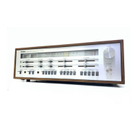
Diagram illustrating the dial mechanism assembly.
Covers FM IF, FM MPX, FM Tuner, and FM Tracking adjustments.
Covers AM IF and AM Tracking adjustments.
Details power supply differences across various regional models.
Shows antenna and speaker connection variations by model.
Lists specific tuner component part number differences by destination.
| Brand | Yamaha |
|---|---|
| Model | CR-400 |
| Category | Stereo Receiver |
| Language | English |