16
DSP-A595
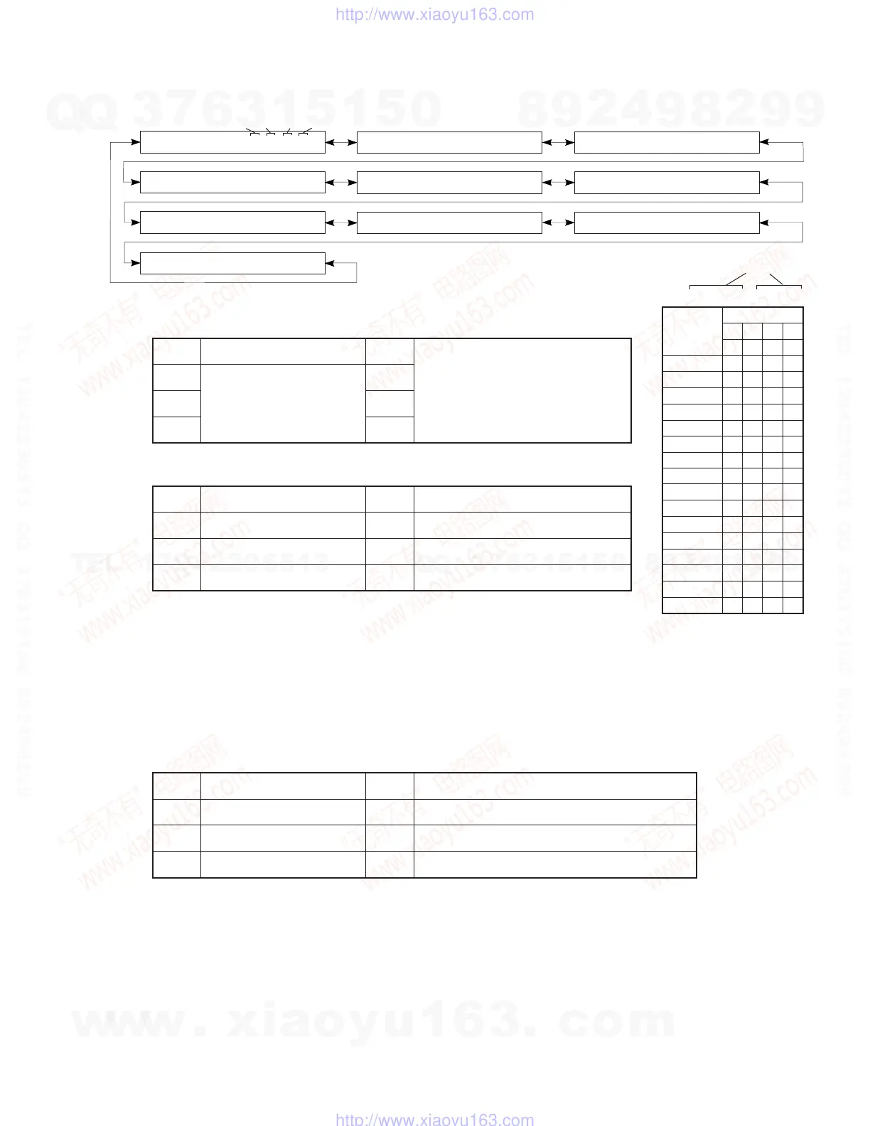
No.10 STATUS FROM DSP MICOM
The status data from the DSP microprocessor is sequentially displayed in a hexadecimal number.
All signal processing before this menu is executed will be held.
[STATUS 0]
<1st Byte>
acmod: If it is 1000B or more with DTS 7.1 signal, the DSP block will be muted.
<2nd Byte>
[Note]
<3rd Byte>
<4th Byte> Always “00”
[STATUS 1] IEC958 channel status bits 00-31 available from DIR2
<1st-byte> bits 00-07
<2nd-byte> bits 08-15
<3rd-byte> bits 16-23
<4th-byte> bits 24-31
[STATUS 2] 4-byte ASCII code of sub CPU version data
[STATUS 3] Displays the check sum of sub microprocessor program area with ASCII 4 bytes in a hexadecimal number.
[STATUS 4] Displays the bit stream information contained in AC-3/DTS signal from the first byte.
[STATUS 5-9] Displays the bit stream information contained in AC-3 signal from the first byte.
bit7 AC3 KARAOKE bit3 On-board write mode
bit6 DIR2 LOCKN bit2 The number of digital inputs is 2 (equivalent to 595)
bit5 DIR2 ERR bit1 DSP is AC3D2 (DTS present)
bit4 AC3D MUTE bit0 RF DEM present
10 DVD/LD 0 00000000
10 DVD/LD 3 00000000
10 DVD/LD 6 00000000
10 DVD/LD 1 00000000
10 DVD/LD 4 00000000
10 DVD/LD 7 00000000
10 DVD/LD 2 00000000
10 DVD/LD 5 00000000
10 DVD/LD 8 00000000
10 DVD/LD 9 00000000
bit7 1 during AC3 decode OK bit3 Demodulator muting (without RF signal)
bit6 1 during DTS decode OK bit2 IEC958 digital format error
bit5 1 during red DTS lock bit1 IEC958 commercial use device bit
bit4
1 for audio other than PCM
linear audio
bit0 IEC958 digital data bit
bit7 Mute request bit3 acmod
0000B:1+1 0001B:1/0
0010B:2/0 0011B:3/0
0100B:2/1 0101B:3/1
0110B:2/2 0111B:3/2
1000B:7.1
bit6 fs bit2
bit5 000B:Analog 001B:32kHz
010B:44.1kHz 011B:48kHz
Others:Don't care
bit1
bit4 bit0
IEC958: Standard to identify the PCM bit stream signal. Digital format error refers to a digital signal with the
sampling frequency undefined (neither 44.1k, 32k nor 48k). Since the operation of each device cannot be
assured at fs outside specifications, the sub-microprocessor handles this status as the forced analog mode
(ignored even if decoding is OK from the detection terminal level), and selects the signal from the analog input
terminal. Since the sub-microprocessor transmits 000B (analog) for STATUS#0 bits 4-6 to the main
microprocessor, the main microprocessor visually operates in the same way as with digital unlocking.
Indicate bit
3210
7654
0 0000
1 0001
2 0010
3 0011
4 0100
5 0101
6 0110
7 0111
8 1000
9 1001
A 1010
B 1011
C 1100
D 1101
E 1110
F1111
bit 7 6 5 4 3 2 1 0
Indicate
0
0
1st 2nd 3rd 4th
w
w
w
.
x
i
a
o
y
u
1
6
3
.
c
o
m
Q
Q
3
7
6
3
1
5
1
5
0
9
9
2
8
9
4
2
9
8
T
E
L
1
3
9
4
2
2
9
6
5
1
3
9
9
2
8
9
4
2
9
8
0
5
1
5
1
3
6
7
3
Q
Q
TEL 13942296513 QQ 376315150 892498299
TEL 13942296513 QQ 376315150 892498299
http://www.xiaoyu163.com
http://www.xiaoyu163.com
 Loading...


