A
1
2
3
4
5
6
7
8
9
10
★
All voltages are measured with a 10M
Ω
/V DC electric
volt meter.
★
Components having special characteristics are marked
and must be replaced with parts having
specifications equal to those originally installed.
★
Schematic diagram is subject to change without notice.
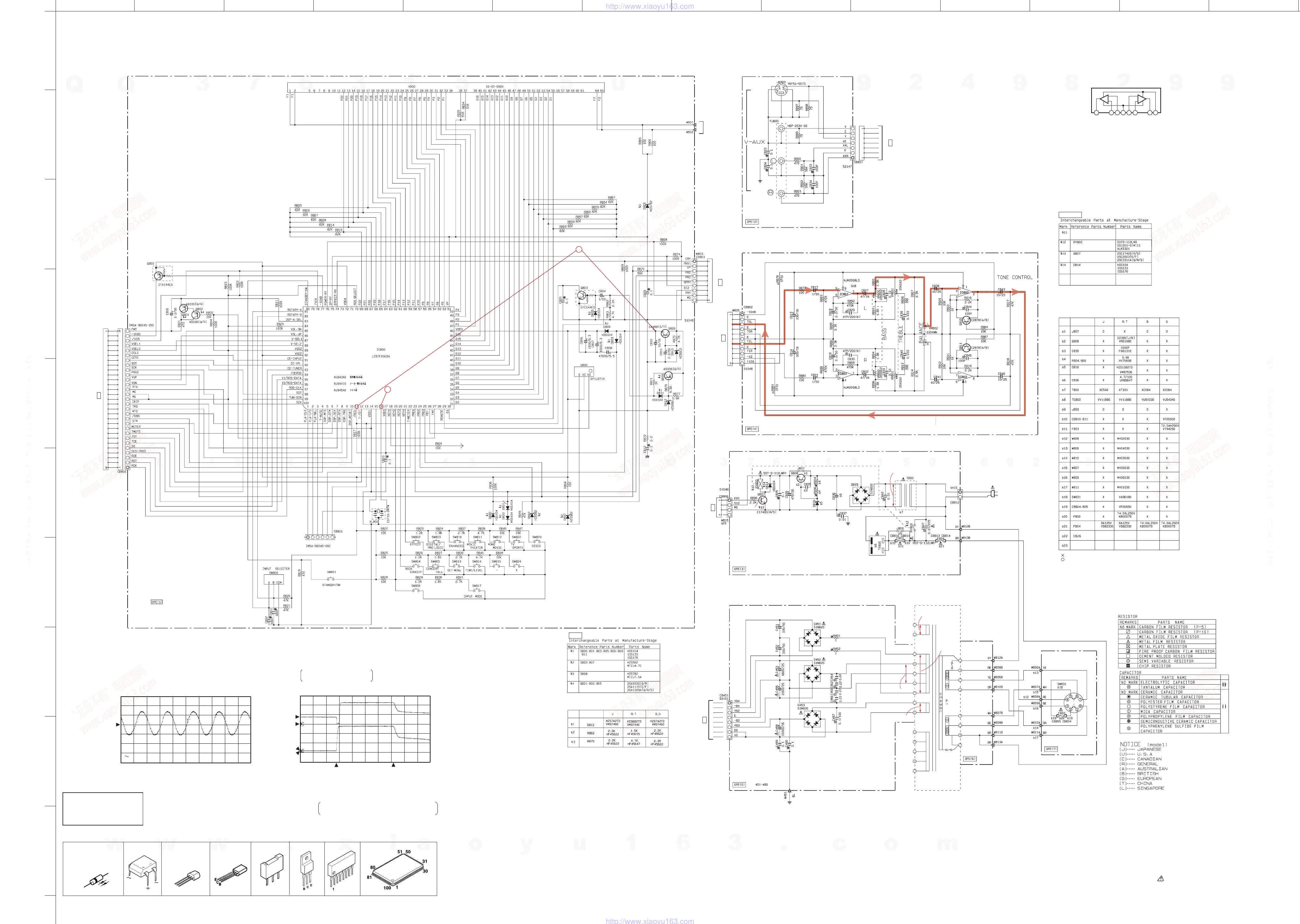
DSP-A595
B
C D
E F
G H I J K L M
N
■ SCHEMATIC DIAGRAM (OPERATION)
PIN CONNECTION DIAGRAM OF DIODES, TRANSISTORS AND IC’s.
2SC4488(S,T)
LC87F65C8A
2SA933A(Q,R)
2SC1740S(R,S)
DTA144ES
DTC144ES
1SS133
1SS176
HSS104
HZS5B2TD
HZS6C2TD
HZS7B2TD
NJM2068LD
Anode
Cathode
S1NB20
HZS7C2TD
HZS12B2TD
2SD2396(J,K)
E
C
B
E
C
B
8
IC801, 802 : NJM2068LD
Dual OP-Amp
1
OUT1
2
–IN1
3
+IN1
4
–Vcc
5
+IN2
6
–IN2
7
OUT2
8
+Vcc
+
–
+
–
• IC800→See page 20~22, IC DATA
Conditions
• INPUT → CD
• VOLUME → minimum(–∞)
• IMPEDANCE
SELECTOR → Upper
• PRO LOGIC → On
51
2SC2878(A,B)
Point 3
(Pin 16 of IC800)
V : 2V/div H : 50nsec/div
AC range 1 : 1 probe
2V SAMPLE 50ns
0V
Point 4
CH1 : Pin 11 of IC800
CH2 : Emitter of Q806
V : 2V/div H : 0.5sec/div
DC range 1 : 1probe
2V 2V SAMPLE 0.5s
0V
CH1
(CH1)
(CH2)
CH2
0V
Disconnect the
power cord from
the AC outlet.
This waveform is not available by pushing the
power switch ON and OFF.
With the POWER
switch turned ON,
connect the
power cord to the
AC outlet.
MAIN L
AC6.5
AC47.7
AC31.2
9.4
4
-29.7
0
29.3
18.8
-19.5
10.0
-29.5
-29.5
-22.2
-22.2
-29.5
-29.5
-29.5
-29.5
-29.3
-26.7
-29.3
-24.1
-26.6
-27.0
-27.0
-27.0
-27.0
-27.0
-27.0
-27.0
-27.0
-27.0
-27.2
-27.2
-27.2
-27.2
-27.3
-27.3
-27.3
4.8
-8.9
-19 .6
-27.0
-27.0
-27.0
-27.0
-27.0
-27.0
-27.0
-27.0
-27.0
-27.2
-27.2
-27.2
-27.2
-27.3
-27.3
4.1
4.1
0
4.8
-11.7
4.3
4.8
4.8
4.8
-11.7
0
0
0
4.8
5.5
6.1
13.2
5.8
12.4
0
13.1
6.5
0
5.5
4.8
-29.7
-22.7
4.8
4.8
0
13.2
4.8
0
0
4.8
4.8
0
4.8
0
4.8
0
0
0
4.4
4.5
0.1
4.8
5.0
4.8
0.1
0
0
4.8
4.8
4.8
4. 8
4.8
5.0
0
2.1
2.5
4.8
0
0
0
0
0
0.3
0
1.9
4.4
4.8
4.8
-27.3
-22.2
-22.2
-29.3
-24.2
-29.3
-24.5
-27.4
-29.6
-19.6
-8.9
Å`
Å`
Å`
-29.5
-29.5
-29.5
-29.5
-29.5
-29.5
0
4.8
4.7
4.8
4.8
4.8
3.2
0
-29.3
-26.7
-29.3
-24.1
-26.6
-29.3
-24.2
-29.3
-24.5
-29.7
Å`
Å`
Å`
Å`
Å`
Å`
Å`
Å`
Å`
Å`
Å`
3
0
0
0
1.9
0
0.3
0
0.2
0.3
0
0
0
13.1
13.1
0.7
AC12.6
0
0.1
-11.7
0.1
0
0.1
11.8
0.1
0
0
0
0
0
0
-11.6
-11.6
11.8
0
0
0
-11.7
0
4.1
4.1
0
SYSTEM & DSP
CONTROL
TONE CONTROL
SUB POWER SUPPLY
POWER SUPPLY
TO INPUT(1) CB104 P49
G-8
TO MAIN(1) CB505
P50
I-4
TO INPUT(1) CB108
P49
I-1
TO
POWER
TRANSFORMER
TO INPUT(2) CB302
P47
D-5
#13
TO MAIN(1) CB506
P50
I-5
TO MAIN(7) CB722
P50
M-9
#17
:NOT USED
:USED
OPE(2),(3),(4)
OPE(1)
330/25
UR84833
MF00407 MF00416 MF00407 MF00407
W815
220/25
UR84822
330/25
UR84833
330/25
UR84833
VOLTAGE
SELECTOR
S.VIDEO
AUDIO
VIDEO
TAPE/MD MON
/EXT.DECODER
(LC876564A-5K19)
+5V
NJM2068LD
NJM2068LD
w
w
w
.
x
i
a
o
y
u
1
6
3
.
c
o
m
Q
Q
3
7
6
3
1
5
1
5
0
9
9
2
8
9
4
2
9
8
T
E
L
1
3
9
4
2
2
9
6
5
1
3
9
9
2
8
9
4
2
9
8
0
5
1
5
1
3
6
7
3
Q
Q
TEL 13942296513 QQ 376315150 892498299
TEL 13942296513 QQ 376315150 892498299
http://www.xiaoyu163.com
http://www.xiaoyu163.com