RX-V1600/DSP-AX1600
14
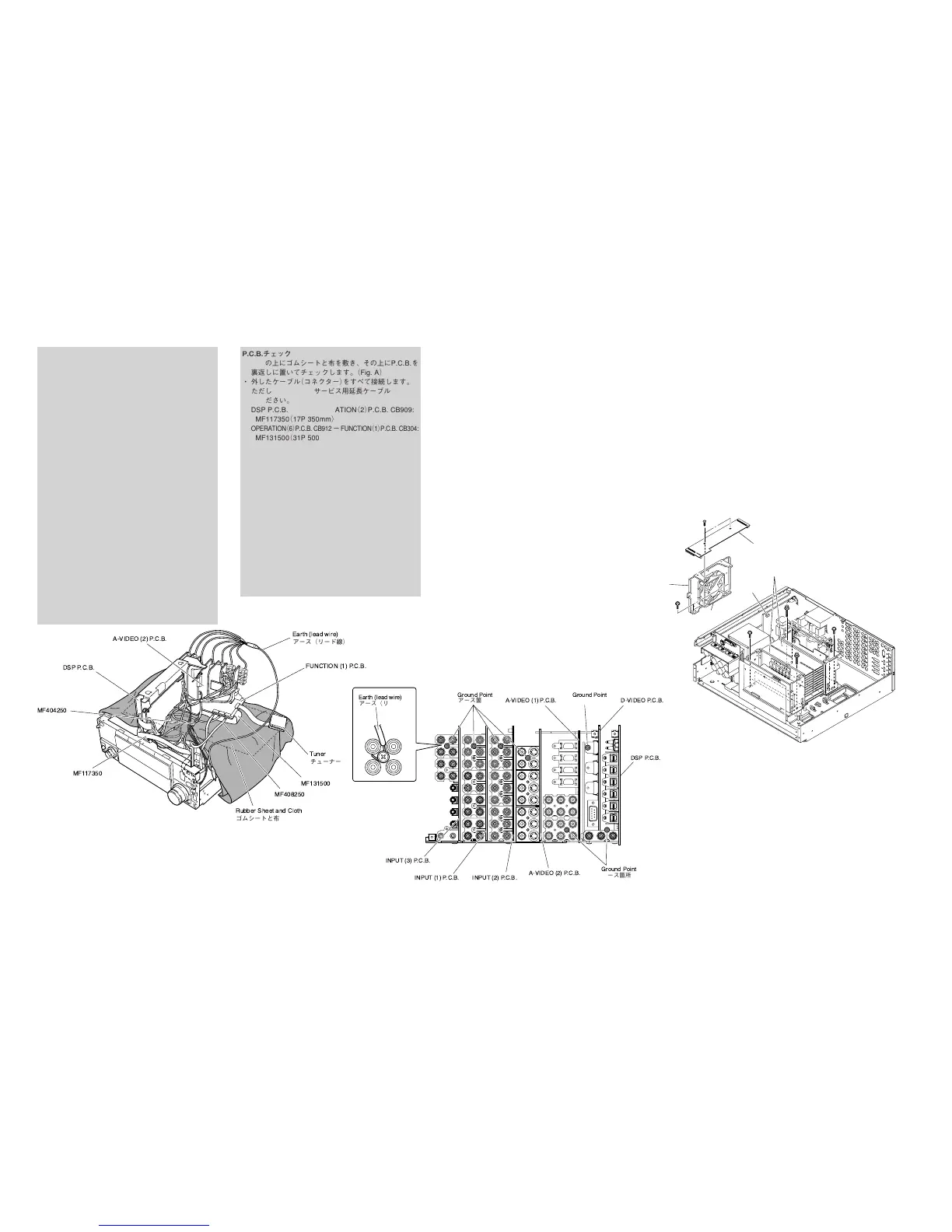
Fig. A
Fig. B
Fig. 6
CB20
I
H
J
J
K
K
Fan
ファン
Frame
フレーム
OPERATION (6) P.C.B.
Amp Unit
アンプユニット
DSP P.C.B.
Rubber Sheet and Cloth
ゴムシートと布
Tuner
チューナー
Earth (lead wire)
アース(リード線)
FUNCTION (1) P.C.B.
A-VIDEO (2) P.C.B.
MF117350
MF131500
MF408250
MF404250
Ground Point
アース箇所
Ground Point
アース箇所
Earth (lead wire)
アース(リード線)
INPUT (1) P.C.B.
INPUT (3) P.C.B.
INPUT (2) P.C.B.
D-VIDEO P.C.B.
A-VIDEO (1) P.C.B.
A-VIDEO (2) P.C.B.
DSP P.C.B.
Ground Point
アース箇所
P.C.B.チェックをする場合には
・ 本機の上にゴムシートと布を敷き、その上にP.C.B.を
裏返しに置いてチェックします。(Fig.A)
・ 外したケーブル(コネクター)をすべて接続します。
ただし次の区間は、サービス用延長ケーブルを使用し
てください。
DSPP.C.B.CB2−OPERATION(2)P.C.B.CB909:
MF117350(17P350mm)
OPERATION(6)P.C.B.CB912−FUNCTION(1)P.C.B.CB304:
MF131500(31P500mm)
FUNCTION(1)P.C.B.CB301−POWER(2)P.C.B.W1:
MF408250(8P250mm)
A-VIDEO(2)P.C.B.W702−POWER(7)P.C.B.CB325:
MF404250(4P250mm)
・ ケーブルを接続する際、極性に注意してください。
・ 本機では下記P.C.B.のアースがリアパネルに接続され
ています。これらのP.C.B.をリアパネルより取り外し
た場合は、リード線等でアースをリアパネルまたは
シャーシに接続してください。(Fig.B)
DSPP.C.B. :PJ1(DIGITALINPUT)
D-VIDEOP.C.B. :CN301(HDMIOUT)
A-VIDEO(1)P.C.B. :PJ602(MONITOROUT)
A-VIDEO(2)P.C.B. :JK703(MONITOROUT)
INPUT(1)P.C.B. :PJ304(MULTICHINPUT)
INPUT(2)P.C.B. :PJ307(ZONE3OUTPUT)
INPUT(3)P.C.B. :PJ309(PREOUT)
When checking the P.C.B.:
• Put the Rubber Sheet and the Cloth over the equipment.
Then place the P.C.B. upside down on the Cloth and
check it. (Fig. A)
• Reconnect all cables (connectors) that have been
disconnected.
Be sure to use the extension cable for servicing for the
following section.
DSP P.C.B. CB2 – OPERATION (2) P.C.B. CB909:
MF117350 (17P 350mm)
OPERATION (6) P.C.B. CB912
–
FUNCTION (1) P.C.B. CB304:
MF131500 (31P 500mm)
FUNCTION (1) P.C.B. CB301 – POWER (2) P.C.B. W1:
MF408250 (8P 250mm)
A-VIDEO (2) P.C.B. W702 – POWER (7) P.C.B. CB325:
MF404250 (4P 250mm)
• When connecting the cable, use care for the polarity.
• In this unit, the ground of P.C.B.s shown below is
connected to the rear panel. When these P.C.B.s are
removed from the rear panel, connect the ground to
the rear panel or chassis, using a lead wire or the like.
(Fig. B)
DSP P.C.B. : PJ1 (DIGITAL INPUT)
D-VIDEO P.C.B. : CN301 (HDMI OUT)
A-VIDEO (1) P.C.B. : PJ602 (MONITOR OUT)
A-VIDEO (2) P.C.B. : JK703 (MONITOR OUT)
INPUT (1) P.C.B. : PJ304 (MULTI CH INPUT)
INPUT (2) P.C.B. : PJ307 (ZONE3 OUTPUT)
INPUT (3) P.C.B. : PJ309 (PRE OUT)
7. Removal of OPERATION (6) P.C.B.
a. Remove 2 screws (H). (Fig. 6)
b. Remove the OPERATION (6) P.C.B. which is connected
directly to the lower P.C.B. with connectors. (Fig. 6)
8. Removal of Fan
a. Remove 2 screws (I). (Fig. 6)
b. Remove CB20. (Fig. 6)
c. Remove the Fan together with the frame by lifting them
up. (Fig. 6)
9. Removal of Amp Unit
a. Remove 4 screws (J) and 4 screws (K). (Fig. 6)
b. Remove the Amp Unit. (Fig. 6)
7. OPERATION(6)P.C.B.の外し方
a.
H
のネジ2本を外します。(Fig.6)
b. OPERATION(6)P.C.B.を取り外します。(Fig.6)
但し、OPERATION(1)P.C.B.は、下方のP.C.B.と直接
コネクター接続されています。
8. ファンの外し方
a.
I
のネジ2本を外します。(Fig.6)
b. CB20を外します。(Fig.6)
c. ファンをフレームといっしょに上方に取り外します。
(Fig.6)
9. アンプユニットの外し方
a.
J
のネジ4本、
K
のネジ4本を外します。(Fig.6)
b. アンプユニットを取り外します。(Fig.6)

 Loading...