Do you have a question about the Yamaha DSP-AX450 and is the answer not in the manual?
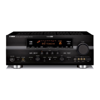
Front panel layout for RX-V550 models in U, C, A, L, R, T, K regions.
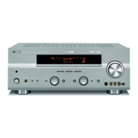
Front panel layout for RX-V550 models in B, G, E regions.
Front panel layout for HTR-5750 models in U, C, A, T, K regions.
Front panel layout for RX-V450 models in U, C, A, L, R, T, K regions.
Front panel layout for RX-V450 models in B, G, E regions.
Front panel layout for HTR-5740 models in U, C, A, T, K regions.
Front panel layout for HTR-5740 models in G, E regions.
Front panel layout for DSP-AX450 model in J region.
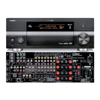
Rear panel layouts for various RX-V550 model configurations.
Rear panel layouts for various HTR-5750 model configurations.
Rear panel layouts for various RX-V450 model configurations.
Rear panel layouts for various HTR-5740 model configurations.
Rear panel layout for DSP-AX450 model in J region.
Layout of remote control for RX-V550/HTR-5750/RX-V450/HTR-5740 models in specified regions.
Layout of remote control for DSP-AX450 model in J region.
Layout of remote control for RX-V450/HTR-5740 models in B, G, E regions.
Layout of remote control for RX-V550 models in B, G, E regions.
Detailed technical specifications for the audio processing and amplification sections.
Technical specifications related to video signal processing and output.
Technical specifications for the FM tuner functionality.
Technical specifications for the AM tuner functionality.
General specifications including power, dimensions, weight, and finish.
Internal view diagram illustrating the component layout for the RX-V550 model.
Internal view diagram for HTR-5750/RX-V450/HTR-5740/DSP-AX450 models.
Step-by-step instructions for disassembling the RX-V550 unit.
Step-by-step instructions for disassembling HTR-5750/RX-V450/HTR-5740/DSP-AX450 units.
Lists all available DIAG menu items and their corresponding sub-menu options.
Procedures for initiating and exiting the diagnostic mode, including protection cancellation.
Explains the information displayed on the FL indicator during DIAG operations.
Provides detailed explanations of specific DIAG menu functions and their outputs.
Technical data and pinout information for the YSS948 IC on the DSP PCB.
Technical data and pinout information for the YSS930 IC on the DSP PCB.
Data and pinout for the M30622MWP-152FP IC on the FUNCTION PCB.
Detailed pinout for the M30622MWP-152FP IC on the FUNCTION PCB.
First part of the system block diagram illustrating signal flow and component interaction.
Second part of the system block diagram showing signal paths and component connections.
Layout diagrams for the DSP Printed Circuit Board (Lead Type and Surface Mount).
Layout diagrams for various FUNCTION Printed Circuit Boards (Lead Type).
Layout diagrams for OPERATION Printed Circuit Boards (Lead Type Device).
Layout diagram for the MAIN Printed Circuit Board (Lead Type Device).
Layout diagrams for POWER Printed Circuit Boards (Lead Type Device).
Layout diagram for the SUBTRANS Printed Circuit Board (Lead Type Device).
Layout diagrams for VIDEO Printed Circuit Boards (Lead and Surface Mount).
Circuit diagram for the DSP section, showing internal components and connections.
Circuit diagrams for various FUNCTION sections, detailing component connections.
Circuit diagrams for the OPERATION sections, illustrating component layouts.
Circuit diagram for the MAIN section, showing major component interconnections.
Circuit diagram for the POWER section, detailing power supply and amplifier circuitry.
Circuit diagram for the SUBTRANS section, showing power supply and control components.
Circuit diagram for the VIDEO section, illustrating signal paths and processing.
Comprehensive list of electrical components used in the unit.
List of chip components, including capacitors and resistors.
Component list for the P.C.B. FUNCTION boards.
Component list for the P.C.B. MAIN board.
List of mechanical parts for the front panel and sub chassis units.
List of mechanical parts for the amplifier unit.
Schematic diagram of the RAV250 remote control unit.
Schematic diagram of the RAV251 remote control unit.
| Type | AV Receiver |
|---|---|
| Audio Channels | 5.1 |
| Signal-to-Noise Ratio | 100 dB |
| Digital Audio Inputs | Optical: 2, Coaxial: 1 |
| Frequency Response | 10 Hz - 100 kHz |
| Surround Sound Formats | Dolby Digital, DTS, Dolby Pro Logic II |
| Input Sensitivity | 200 mV |
| Input Impedance | 47k ohms |
| Video Inputs | 3 x S-Video |
| Video Outputs | Composite: 1, S-Video: 1 |


 Loading...