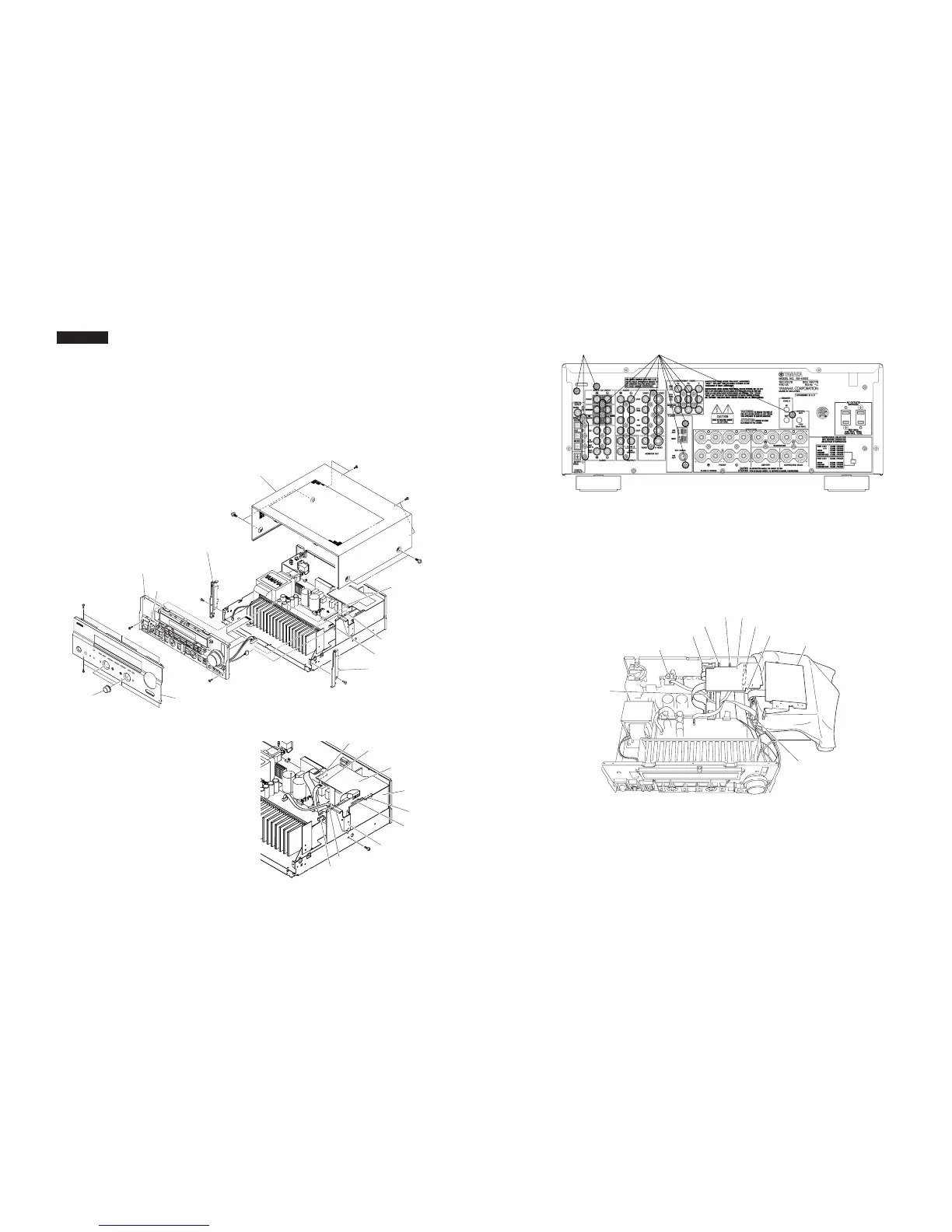
■ DISASSEMBLY PROCEDURES
Fig. 1
(Remove parts in the order as numbered.)
Disconnect the power cable from the AC outlet.
1. Removal of Top Cover
a. Remove 4 screws (1) and 4 screws (2). (Fig. 1)
b. Slide the Top Cover rearward to remove it. (Fig. 1)
2. Removal of Front Panel Unit
a. Remove 2 Knobs. (Fig. 1)
b. Remove 6 screws (3) and then remove the Front Panel Unit.
(Fig. 1)
3. Removal of Plate Side
a. Remove 2 push rivets (4). (Fig. 1)
b. Remove the Plate Side. (Fig. 1)
Fig. 2
5. Removal of DSP P.C.B.
a. Remove 1 screw (6). (Fig. 2)
b. Remove 7 screws (7). (Fig. 3)
c. Remove CB2. (Fig. 2)
d. Lift up the FUNCTION (2) P.C.B. and remove the CB1. (Fig. 2)
e. Remove the DSP P.C.B. with the Support/DSP. (Fig. 2)
Fig. 3
6. Removal of FUNCTION (1) ~ (8) P.C.B.s and Tuner
a. Remove CB307, CB351, CB502 and CB503. (Fig. 2)
b. Remove 21 (U, C, A models) / 20 (except U, C, A models)
screws (8). (Fig. 3)
c. Remove FUNCTION (1) ~ (8) P.C.B.s. and the Tuner. (Fig. 4)
RX-V550
4. Removal of Sub Chassis Unit
a. Remove 2 screws (5) and then slide the Sub Chassis Unit
forward. (Fig. 1)
b. Loosen the harness fixture fixing the cable.
c. Remove CB306, CB309, CB505 and CB863 and then remove
the Sub Chassis Unit. (Fig. 1)
Fig. 4
 Loading...


