2-1
GB
EMU01206
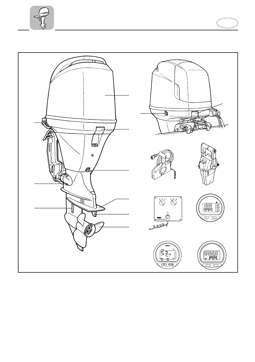
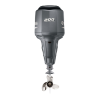
MAIN COMPONENTS
TRIP TIME BATT
Km/h
knot
mph
km
mile
SPEED
YAMAHA
set
mode
q
w
e
r
t
y
u
i
o
000301
w
000300
YAMAHA
set
mode
P S
mpg
Km/L
gph
I/h
ECON SYNCTTL
FUEL MANAGEMENT
!0
!1
!2
!3
!4
!5 !6
701061
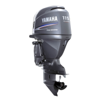
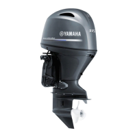
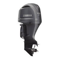
1 Top cowling
2 Top cowling lock levers
3 Engine oil drain bolt
4 Anti-cavitation plate
5 Trim tab (Anode)
* 6 Propeller
7 Cooling water inlet
8 Anode
9 Flushing device
0 Power trim and tilt switch
* q Remote control box (Side mount type)
* w
Remote control box (Binnacle mount type)
* e Switch panel (For use with w)
* r Digital speedometer
* t Digital tachometer
* y Fuel management meter
* May not be exactly as shown; also may not
be included as standard equipment on all
models.
68V-9-72 (GB,F,ES)-2 4/20/01 11:50 AM Page 4