EasyManua.ls Logo

Yamaha MX-2000 Service Manual

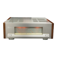
Yamaha MX-2000
20 pages
To Next Page IconTo Next Page
Page #1 background imageLoading...
Page #1 background image
ERE0 POWER AMPLIFIER
CONTENTS
f
IMPORTANT
NOTICE
This manual has been provided for the use of authorized Yamaha Retailers and their service personnel.
It has been
assumed that basic service procedures inhennt to the industry, and more specifically Yamaha
Products, are already known and understcad by
the
users,
and
have therefore not been restated.
WARNING:
Failure to follow appropriate service and safety procedures when servicing this product
may result in
personal injury, destruction of expensive Eamponentr
and
failure of the
product
to
perform as specified. For these reasons,
we
advise all Yamaha product ownel
rhat all sewib~ required should
be
performed by an authorized Yamaha Retailer or
th
appointed service representative.
IMPORTANT:
The presentation or sale of this manual
to
any individual or firm does not ~onstitute
authorization, certification
or
remgnitidn of any appllcaMe technical aapabillties,
or
establish a principle-agent relationship of any form.
The
data provided is believed
to
be accurate and applicable to the unit(s) iddftxtted
an
the
wver.
The
research, engineering, and service departments of
Yamaha are continually striving
to
imptwe Yamaha
products. Modifications
are,
therefore, inevitable and specifications are subjectt~
chaage
wi&out notice or
obligation to retrofit. Should any discrepancy appear
to
exist, please contact the distributor's Servim
Division.
WARNING:
Static discharges can destroy expensive components. Discharge any staticelectricity your
body may have accumulated by grounding yourself to the ground buss in
the
unit (heavy
gauge black wires
c~lncct
to
this buss).
IMPORTANT:
Turn the unit OFF during d~sassembly and parts replacement. Recheck all work before
you apply
power
to
the unit.
L
-
-
- -
TO SERVICE PERSONNEL
.................
1 ADJUSTMENTS
........................
4
FRONTIREAR PANELS
...................
1 PRINTED CIRCUIT BOARD
.............
5
-
9
SPECIFICATIONS
.......................
2
SCHEMATIC DIAGRAM
..................
10
BLOCK DIAGRAM
......................
2 WIRING..
...........................
11
INTERNAL
VIEW..
.....................
3
PARTSLIST..
....................
12-20
DISASSEMBLY PROCEDURES
..............
4
YAMAHA
CORPORATION
PO.Box
1.
Harnarnatsu.
Japan
1.35K-604
liq@
Printed
in
Japan
'88.8
Question and Answer IconNeed help?

Do you have a question about the Yamaha MX-2000 and is the answer not in the manual?

Yamaha MX-2000 Specifications

General IconGeneral
TypeStereo Power Amplifier
Weight25 kg
Total Harmonic Distortion0.003% (20Hz - 20kHz)
Damping Factor150
Input Sensitivity1.23V
Signal to Noise Ratio125dB

Summary

TO SERVICE PERSONNEL

Critical Components Information

Components marked 'A' require exact replacement for specified performance and safety.

Leakage Current Measurement

Post-service check to ensure proper insulation of exposed conductive surfaces from supply circuits.

SPECIFICATIONS

Performance Specifications

Detailed technical specifications including output power, frequency response, and distortion levels.

BLOCK DIAGRAM

Amplifier Functional Block Diagram

Illustrates the main functional blocks and signal flow within the amplifier.

INTERNAL VIEW

DISASSEMBLY PROCEDURES

ADJUSTMENTS

Idling Voltage Adjustment

Procedure to adjust VR201 for correct idling voltage on the main circuit board.

Power Meter Calibration

Steps to adjust VR401/VR402 and VR403/VR404 for accurate power meter readings.

PRINTED CIRCUIT BOARD (Main Circuit Board)

Main Circuit Board Pattern Side Layout

Shows the pattern side layout of the main circuit board, indicating component placement.

PRINTED CIRCUIT BOARD (Power Supply Circuit Board 1)

Power Supply Circuit Board (1) Pattern Side Layout

Displays the pattern side layout for the first power supply circuit board.

PRINTED CIRCUIT BOARD (Power Supply Circuit Board 2)

Power Supply Circuit Board (2) Pattern Side Layout

Displays the pattern side layout for the second power supply circuit board.

PRINTED CIRCUIT BOARD (Meter Circuit Board 2 / Protection Circuit Board)

PRINTED CIRCUIT BOARD (Input Circuit Board / Meter Circuit Board 1)

WIRING

Internal Wiring Diagram

Illustrates the wiring connections between major internal components and boards.

PARTS LIST (Electrical - Section 1)

Electrical Parts: Capacitors

Lists various types of capacitors with part numbers and specifications.

PARTS LIST (Electrical - Section 2)

EXPLODED VIEW

Related product manuals