EasyManua.ls Logo

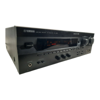
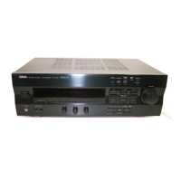
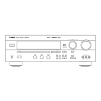
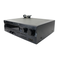
Yamaha RX-V496 Service Manual

Yamaha RX-V496
74 pages
To Next Page IconTo Next Page
Page #1 background imageLoading...
Page #1 background image
SERVICE MANUAL
IMPORTANT NOTICE
This manual has been provided for the use of authorized YAMAHA Retailers and their service personnel.
It has been assumed that basic service procedures inherent to the industry, and more specifically YAMAHA
Products, are already known and understood by the users, and have therefore not been restated.
WARNING:Failure to follow appropriate service and safety procedures when servicing this product
may result in personal injury, destruction of expensive components, and failure of the
product to perform as specified. For these reasons, we advise all YAMAHA product
owners that any service required should be performed by an authorized YAMAHA
Retailer or the appointed service representative.
IMPORTANT:The presentation or sale of this manual to any individual of firm does not constitute
authorization, certification or recognition of any applicable technical capabilities,
or establish a principle-agent relationship of any form.
The data provided is believed to be accurate and applicable to the unit(s) indicated on the cover. The research,
engineering, and service departments of YAMAHA are continually striving to improve YAMAHA products.
Modifications are, therefore, inevitable and specifications are subject to change without notice or obligation
to retrofit. Should any discrepancy appear to exist, please contact the distributor's Service Division.
WARNING:Static discharges can destroy expensive components. Discharge any static electricity
your body may have accumulated by grounding yourself to the ground buss in the unit
(heavy gauge black wires connect to this buss).
IMPORTANT:Turn the unit OFF during disassembly and part replacement. Recheck all work before
you apply power to the unit.
100704
AV RECEIVER
RX-V496/RX-V496RDS
HTR-5240/HTR-5240RDS
TO SERVICE PERSONNEL...........................................1
REMOTE CONTROL PANELS.......................................1
FRONT PANELS.............................................................2
REAR PANELS...........................................................3~4
SPECIFICATIONS.......................................................5~6
INTERNAL VIEW............................................................7
DISASSEMBLY PROCEDURES....................................7
SELF DIAGNOSIS FUNCTION................................8~19
FACTORY PRESET......................................................20
CONTENTS
AMP ADJUSTMENT.....................................................21
TUNER ADJUSTMENT...........................................22~25
IC DATA..................................................................26~34
DISPLAY DATA...........................................................35
BLOCK DIAGRAM..................................................36~39
PRINTED CIRCUIT BOARD...................................40~59
SCHEMATIC DIAGRAM.........................................60~67
PARTS LIST............................................................68~85
REMOTE CONTROL TRANSMITTER...................86~87

Table of Contents

Other manuals for Yamaha RX-V496

Questions and Answers:

Yamaha RX-V496 Specifications

General IconGeneral
TypeAV Receiver
Channels5.1
Amplifier TypeDiscrete
Input Sensitivity200 mV (line)
Weight9.8 kg
Tuner SectionFM/AM
Preset Stations40
Surround Sound FormatsDolby Digital, Dolby Pro Logic
Frequency Response10 - 100000 Hz
Total Harmonic Distortion0.06 %
Input Sensitivity/Impedance200 mV / 47 kΩ
Dimensions151 mm
Signal-to-Noise Ratio96dB (line)

Summary

Service Personnel Guidelines

Critical Components Handling

Components with special characteristics marked must be replaced with identical parts.

Leakage Current Measurement

Verify insulation of conductive surfaces after service.

Safety Cautions

Fuse replacement warning for fire protection.

Chemical Content Warning

Warning about lead and other chemical content in components.

Remote Control Panels

U,C,R,T, A and L Models Layout

Layout of remote control buttons for U, C, R, T, A, and L models.

B and G Models Layout

Layout of remote control buttons for B and G models.

Front Panel Views

RX-V496 Model Variants

Front panel appearance for RX-V496 variants based on region and color.

RX-V496RDS Model Variants

Front panel appearance for RX-V496RDS variants based on region and color.

HTR-5240 Model Variants

Front panel appearance for HTR-5240 variants based on region and color.

HTR-5240RDS Model Variants

Front panel appearance for HTR-5240RDS variants based on region and color.

Rear Panel Connections

RX-V496/HTR-5240 U Model Rear

Rear panel connection layout for the RX-V496/HTR-5240 U model.

RX-V496/HTR-5240 C Model Rear

Rear panel connection layout for the RX-V496/HTR-5240 C model.

RX-V496 R Model Rear

Rear panel connection layout for the RX-V496 R model.

RX-V496/HTR-5240 T Model Rear

Rear panel connection layout for the RX-V496/HTR-5240 T model.

Technical Specifications

Audio Section Specifications

Technical audio performance specifications including output power and distortion.

FM Section Specifications

FM tuner reception specifications like tuning range and sensitivity.

Audio and FM Specifications Details

Detailed Audio Performance

Detailed audio performance metrics like output power, distortion, and signal-to-noise ratio.

FM Reception Parameters

FM reception parameters including tuning range, sensitivity, and selectivity.

General and Specific Specifications

AM Section Specifications

AM tuner reception specifications, including tuning range and sensitivity.

Video Section Specifications

Video signal type, level, and response specifications.

General Unit Specifications

General unit specifications including power supply, consumption, dimensions, and weight.

Impedance Selector Warning

Warning about changing impedance selector while unit is powered on.

Internal View and Disassembly

Internal Unit Layout

Diagram showing the internal component layout of the unit.

Top Cover Removal

Procedure for removing the top cover by unscrewing.

Front Panel Removal

Procedure for removing the front panel and its components.

Main Amplifier PCB Preparation

Steps before checking/replacing parts on the main amplifier PCB.

Self Diagnosis Function Overview

Purpose and Operation

Overview of the self-diagnosis function for locating faulty parts.

Starting and Cancelling the Function

Instructions on starting and exiting the self-diagnosis function.

Diagnostic Program Start Settings

Default settings used when initiating the diagnostic program.

Start-up Display Information

Information displayed on the front panel upon starting the diagnostic program.

Self Diagnosis Operation Details

Selecting Diagnostic Menus

Methods for selecting diagnostic menus using front panel keys or remote control.

Available Functions During Diagnosis

Functions that can be used while the diagnosis program is running.

Diagnosis Default Status Settings

Default settings for various parameters within the diagnostic menus.

Exiting the Diagnosis Mode

Procedures for exiting the self-diagnosis mode and returning to normal operation.

Self Diagnosis Display Information

FL Display at Program Start

Details on FL display content during diagnostic program startup.

Protection History Display

Examples of how protection history is shown in the diagnostic display.

Diagnostic Menu Selection Methods

Front Panel Key Selection

How to navigate menus using front panel controls.

Remote Control Unit Selection

How to navigate menus using the remote control.

Diagnosis Function Contents

No.1 Analog Through Test

Diagnostic test for analog signal path and bypass operation.

Diagnosis Function Contents (Continued)

No.2 DSP Through Test

Diagnostic test for DSP signal path with automatic input discrimination.

Diagnosis Function Contents (Continued)

No.3 AC-3/DTS Through Test

Diagnostic test for digital input handling AC-3/DTS signals.

No.4 Pro Logic Test

Diagnostic test for PRO LOGIC (Auto Balance OFF) and Effect OFF.

Diagnosis Function Contents (Continued)

No.5 Speakers Set Test

Diagnostic test for speaker output channels based on sub-menu settings.

Diagnosis Function Contents (Continued)

No.6 Display Check

Checking FL display status and detecting FL drive port defects.

No.7 Manual Test

Testing audio output to specified channels using the built-in noise generator.

No.8 Factory Preset Initialization

Initializing backup RAM, including DSP program and set menu contents.

Diagnosis Function Contents (Continued)

No.9 AD Data Check

Checking A/D conversion values for microcomputer inputs like key scan and protection.

Diagnosis Function Contents (Continued)

No.10 Status Information from DSP

Displaying DSP block status data sequentially in hexadecimal.

Diagnosis Function Contents (Continued)

No.11 EEPROM Writing Function

Confirming EEPROM check sum and performing data writing.

No.12 Check Sum/Version/Exit

Displaying microcomputer version, check sum, port settings, and exiting mode.

Factory Preset Settings

Input Selector Presets

Factory default program assignments for input selectors.

Effect Level Presets

Factory default preset values for effect levels.

DSP Program Presets

Factory default delay preset values for DSP programs.

Set Menu Presets

Factory default settings for various menu items.

Preset Station Data

Factory preset FM and AM station data.

Amplifier Adjustment Procedures

Idling Current Confirmation

Procedure to confirm and adjust idling current of the main amplifier.

Tuner Adjustment Procedures

Required Measuring Instruments

List of instruments required for tuner adjustment procedures.

Dummy Antenna Setup

Diagrams for FM and AM dummy antenna connections.

Tuner Adjustment Test Points

Diagram showing test points for tuner adjustment.

FM Tuning Adjustment

FM Adjustment Preparation

Preliminary steps and notes before performing FM adjustment.

FM Measurement Connection Diagrams

Diagrams showing measurement instrument connections for FM adjustment.

FM Sensitivity Verification

Procedure for verifying FM signal sensitivity.

FM Adjustment Step Table

Table detailing adjustment items, signal, test points, and ratings.

FM Tuning Adjustment (Continued)

FM Adjustment Step Table (Continued)

Continuation of the table detailing FM adjustment steps and parameters.

AM Tuning Adjustment

AM Measurement Connection Diagrams

Diagrams showing instrument connections for AM adjustment.

AM Adjustment Step Table

Table detailing AM adjustment items, signal, test points, and ratings.

Integrated Circuit Data

IC501: M30217MA-A202FP Microcomputer Pinout

Pin configuration and function description for the M30217MA-A202FP microcomputer.

Integrated Circuit Data (Continued)

IC501 Microcomputer Pin Details

Detailed pin assignments and functions for the microcomputer.

Integrated Circuit Data (Continued)

IC501 Microcomputer Pin Details (Continued)

Continued pin configuration for the microcomputer.

IC107 BU2090 Driver IC Pinout

Pinout and function of the BU2090 IC for serial/parallel data handling.

Integrated Circuit Data (Continued)

IC3 YM3436DK Digital Interface Receiver Pinout

Pinout and function of the YM3436DK for digital interface reception.

Integrated Circuit Data (Continued)

IC4 YSS918D-F DSP Decoder IC Pinout

Pinout and function of the YSS918D-F DSP decoder IC.

Integrated Circuit Data (Continued)

IC4 YSS918D-F DSP Decoder IC Pinout (Continued)

Continued pinout and function of the YSS918D-F IC.

Integrated Circuit Data (Continued)

IC4 YSS918D-F DSP Decoder IC Pinout (Continued)

Further pinout and functional details for the YSS918D-F IC.

Integrated Circuit Data (Continued)

IC5 M5M51288BKJ SRAM IC Pinout

Pinout and function of the 1M SRAM IC.

Integrated Circuit Data (Continued)

IC6 CS4227 Codec IC Pinout

Pinout and function of the CS4227 Codec IC for A/D and D/A conversion.

Display Data and Connections

Display Pin Connections

Pin numbering and connection assignments for the display module.

Display Grid Assignments

Mapping of segment numbers to display grid positions.

Display Anode Connections

Anode connection details for display segments across different grids.

System Block Diagrams (1/2)

Input Signal Flow (1/2)

Block diagram section showing input signal flow.

Input Signal Flow (2/2)

Second part of the input signal flow block diagram.

DSP Circuitry Block

Block diagram section detailing the DSP and decoder circuitry.

Operation Signal Flow (1/2)

Block diagram section showing operational signal flow.

Operation Signal Flow (2/2)

Second part of the operational signal flow block diagram.

System Block Diagrams (2/2)

FM Antenna Input Stage

FM antenna input stage in the block diagram.

Ground Connections

Ground connections within the block diagram.

AM Antenna Input Stage

AM antenna input stage in the block diagram.

Printed Circuit Board Layouts

Tuner PCB Assembly Variants

List of tuner PCB assemblies by market and model.

Tuner PCB Layout (B/G RDS, Lead Type)

Foil side layout of the tuner PCB for B/G models (Lead Type).

Tuner PCB Semiconductor Locations

Location reference for semiconductors on the tuner PCB.

Printed Circuit Board Layouts (Continued)

Tuner PCB Layout (J,U,C,R,T,A,L Models, Lead Type)

Foil side layout of tuner PCB for J,U,C,R,T,A,L models (Lead Type).

Tuner PCB Layout (J,U,C,R,T,A,L Models, Lead & SMD)

Foil side layout of tuner PCB for J,U,C,R,T,A,L models (Lead & SMD).

Tuner PCB Semiconductor Locations (Lead & SMD)

Location reference for semiconductors on tuner PCB (Lead & SMD).

Printed Circuit Board Layouts (Continued)

Main PCB (2) Layout (J,U,C,A,B,G,L Models)

Foil side layout of Main PCB (2) for J,U,C,A,B,G,L models.

Main PCB (2) Semiconductor Locations

Location reference for semiconductors on Main PCB (2).

Main PCB (2) Layout (R and T Models)

Foil side layout of Main PCB (2) for R and T models.

Printed Circuit Board Layouts (Continued)

Main PCB (6) Layout

Foil side layout of Main PCB (6).

Main PCB (5) Layout

Foil side layout of Main PCB (5).

Main PCB (7) Layout

Foil side layout of Main PCB (7).

Main PCB (3) Layout

Foil side layout of Main PCB (3).

Main PCB (4) Layout

Foil side layout of Main PCB (4).

Printed Circuit Board Layouts (Continued)

Main PCB (1) Layout

Foil side layout of Main PCB (1).

Printed Circuit Board Layouts (Continued)

Operation PCB (4) Layout

Foil side layout of Operation PCB (4).

Operation PCB (5) Layout

Foil side layout of Operation PCB (5).

Operation PCB (7) Layout

Foil side layout of Operation PCB (7).

Operation PCB (6) Layout

Foil side layout of Operation PCB (6).

Printed Circuit Board Layouts (Continued)

DSP PCB Layout

Foil side layout of the DSP PCB.

Printed Circuit Board Layouts (Continued)

Operation PCB (1) Layout

Foil side layout of Operation PCB (1).

Operation PCB (2) Layout

Foil side layout of Operation PCB (2).

Operation PCB (3) Layout

Foil side layout of Operation PCB (3).

Printed Circuit Board Layouts (Continued)

Input PCB (4) Layout

Foil side layout of Input PCB (4).

Input PCB (2) Layout

Foil side layout of Input PCB (2).

Input PCB (3) Layout

Foil side layout of Input PCB (3).

Printed Circuit Board Layouts (Continued)

Input PCB (1) Layout

Foil side layout of Input PCB (1).

Schematic Diagram: Input (1/2)

Phono (MM) EQ Amplifier Schematic

Schematic of the Phono EQ amplifier circuit.

Main Level Control Schematic

Schematic of the main level control circuitry.

6-Channel Selector Schematic

Schematic of the 6-channel selector circuit.

Schematic Diagram: Input (2/2)

Digital Signal Detector Selector Schematic

Schematic of the digital signal detector and selector.

Volume Amplifier Schematic

Schematic of the volume amplifier stages.

Schematic Diagram: Operation (1/2)

Microcomputer Schematic

Schematic showing the microcomputer and its connections.

Tone Control Circuitry Schematic

Schematic of the tone control circuitry.

Power Down Detection Schematic

Schematic for power down detection circuitry.

Schematic Diagram: DSP

DIR2 Digital Interface Receiver Schematic

Schematic of the DIR2 digital interface receiver.

DSP Amplifier Stages Schematic

Schematic of the DSP amplifier stages.

Schematic Diagram: Operation (2/2)

Main Power Amplifier Schematic

Schematic of the main power amplifier circuits.

Rear Power Amplifier Schematic

Schematic of the rear power amplifier circuits.

Center Power Amplifier Schematic

Schematic of the center power amplifier circuit.

S-Video Selector and Amplifier Schematic

Schematic of the S-Video selector and amplifier.

Schematic Diagram: Main Amplifiers

Main Power Amplifier Schematic

Schematic of the main power amplifier circuit.

Rear Power Amplifier Schematic

Schematic of the rear power amplifier circuits.

Center Power Amplifier Schematic

Schematic of the center power amplifier circuit.

Schematic Diagram: Tuner (J, U, C, R, T, A, L Models)

IC1 LA1266 AM/FM IF Schematic

Schematic for IC1 (LA1266) AM/FM IF section.

IC2 LC72131 PLL Controller Schematic

Schematic for IC2 (LC72131) PLL controller.

IC3 LA3401 MPX Schematic

Schematic for IC3 (LA3401) MPX section.

Discriminator Balance Adjustment Point

Adjustment point for discriminator balance.

Schematic Diagram: Tuner (B, G Models RDS)

IC1 LA1266 AM/FM IF Schematic (B/G RDS)

Schematic for IC1 (LA1266) AM/FM IF section for B/G RDS models.

IC2 LC72131 PLL Controller Schematic (B/G RDS)

Schematic for IC2 (LC72131) PLL controller for B/G RDS models.

IC4 LC72722 RDS Decoder Schematic

Schematic for IC4 (LC72722) RDS decoder.

Discriminator Balance Adjustment

Adjustment point for discriminator balance.

Parts List

Electrical Parts List

List of electrical components with part numbers and descriptions.

Parts List Abbreviations

Key to abbreviations used in the parts list.

Parts List (Continued)

DSP PCB Parts List

Parts list for the DSP printed circuit board.

Parts List (Continued)

DSP and Input PCB Parts List

Parts list for DSP and Input PCBs.

Parts List (Continued)

Operation and Main PCB Parts List

Parts list for Operation and Main PCBs.

Parts List (Continued)

Operation and Main PCB Parts List (Continued)

Continued parts list for Operation and Main PCBs.

Parts List (Continued)

Operation PCB Parts List

Parts list for the Operation printed circuit board.

Parts List (Continued)

Operation PCB Parts List (Continued)

Continued parts list for the Operation PCB.

Parts List (Continued)

Operation and Main PCB Parts List (Continued)

Parts list for Operation and Main PCBs.

Parts List (Continued)

Main PCB Parts List

Parts list for the Main printed circuit board.

Parts List (Continued)

Main PCB Parts List (Continued)

Continued parts list for the Main PCB.

Parts List (Continued)

Tuner PCB Parts List (Lead Type)

Parts list for the Tuner printed circuit board (Lead Type).

Parts List (Continued)

Tuner PCB Parts List (Continued)

Continued parts list for the Tuner PCB.

Tuner PCB Parts List (Lead Type & SMD)

List of Tuner PCB parts for Lead Type & SMD variants.

Parts List (Continued)

Tuner PCB Parts List (Chip Resistors)

Continued parts list for Tuner PCB, including Chip Resistors.

Chip Resistors List

Detailed list of chip resistors with part numbers.

Mechanical Parts Information

Exploded View Diagram

Exploded view diagram showing mechanical part assembly.

Mechanical Parts List

List of mechanical parts with part numbers, descriptions, and remarks.

Mechanical Parts Information (Continued)

Mechanical Parts List (Continued)

Continued list of mechanical parts.

Mechanical Parts Information (Continued)

Accessories List

List of included accessories like remote control and antennas.

Remote Control Transmitter

Remote Control Schematic Diagram

Schematic diagram of the remote control transmitter circuit.

Remote Control Functional Key List

Table mapping remote control key numbers to functions and devices.

Remote Control Transmitter (Continued)

Yamaha Code List (NEC Format)

Table of Yamaha remote control codes in NEC format for different devices.

Related product manuals