CONNECTING RODS AND PISTONS
EB404403
CHECKING THE CYLINDERS AND PISTONS
The following procedure applies to all of
the cylinders and pistons.
1. Check:
• piston wall
• cylinder wall
Vertical scratches → Replace the
crankcases, and the piston and piston
rings as a set.
2. Measure:
• piston-to-cylinder clearance
▼ ▼ ▼ ▼ ▼ ▼ ▼ ▼ ▼ ▼ ▼ ▼ ▼ ▼ ▼ ▼ ▼ ▼ ▼ ▼ ▼ ▼ ▼ ▼ ▼ ▼ ▼
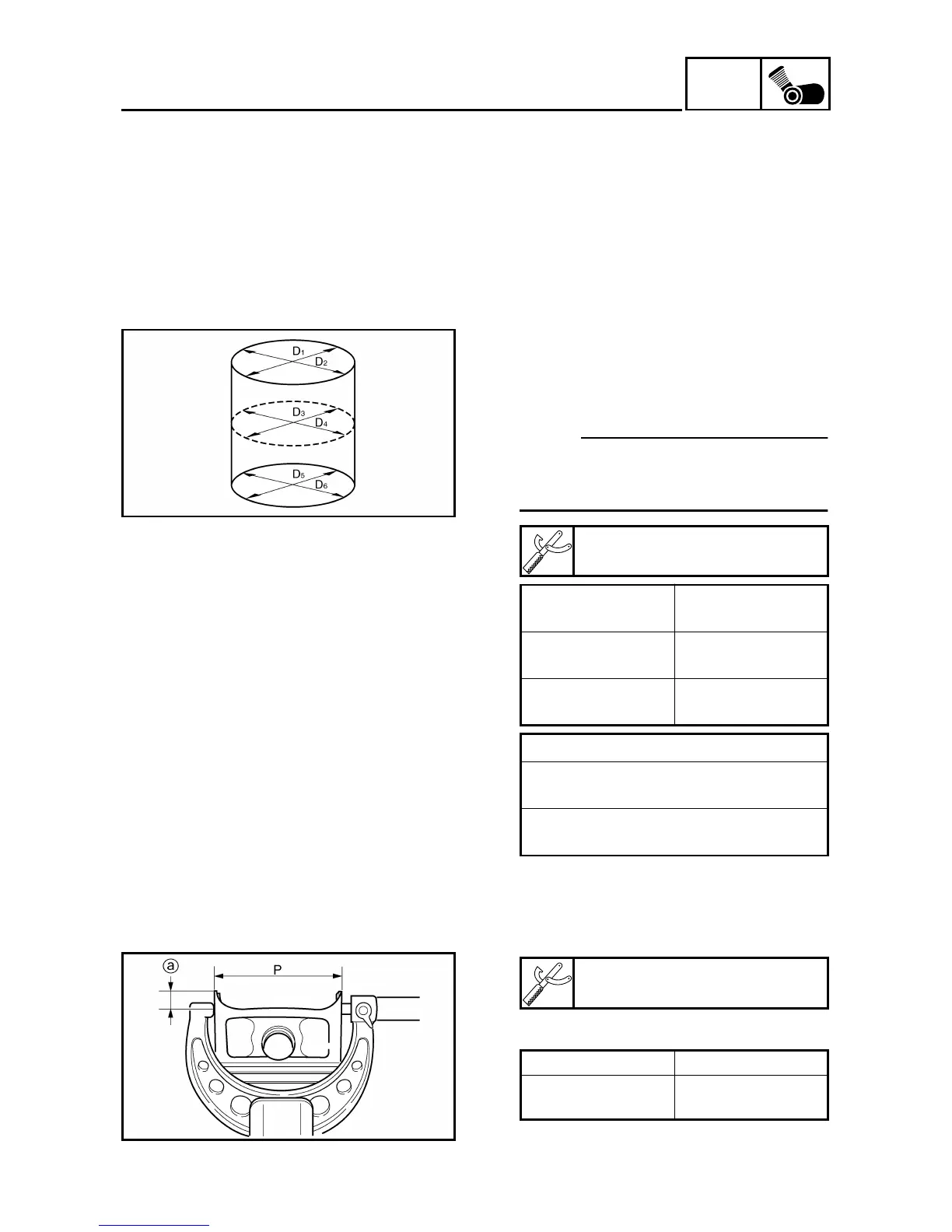
a. Measure cylinder bore “C” with the
cylinder bore gauge.
NOTE:
Measure cylinder bore “C” by taking
side-to-side and front-to-back measure-
ments of the cylinder. Then, find the
average of the measurements.
b. If out of specification, replace the
crankcases, and the pistons and pis-
ton rings as a set.
c. Measure piston skirt diameter “P”
with the micrometer.
a 10 mm (0.39 in) from the bottom edge
of the piston
d. If out of specification, replace the pis-
ton and piston rings as a set.
Cylinder bore gauge
90890-03017
Cylinder bore “C”
72.000 ~ 72.008 mm
(2.8346 ~ 2.8350 in)
Maximum taper
“T”
0.05 mm
(0.0016 in)
Out of round “R”
0.05 mm
(0.0016 in)
“C”= maximum of D1
~
D6
“T” = maximum of D1, or D2 – maxi-
mum of D
5 or D6
“R” = maximum of D1, D3 or D5 – mini-
mum of D
2, D4 or D6
Micrometer
90890-03008
Piston size “P”
Standard
71.954 ~ 71.972 mm
(2.8328 ~ 2.8335 in)
 Loading...