Digital Controller SIO Driver
GP-Pro EX Device/PLC Connection Manual
79
5 Cable Diagram
The cable diagram shown below may differ from that recommended by Yamatake Corporation. Please be assured,
however, that there is no operational problem in applying the cable diagram shown in this manual.
• The FG pin on the External Device must be D-class grounded. Refer to your External Device manual for
details.
• The SG and FG are connected inside the Display. If you connect the External Device to the SG, do not form
any short-circuit loop in the system design.
• Consult your External Device manual for the pin No. on the External Device side. It varies depending on the
additional function.
• If the communication is not stable because of noise or other factors, connect an isolation unit.
• Recommended cable
Cable Diagram 1
Company Name Model
Fujikura Densen,
Ltd.
Duplex IPEV-S-0.9mm
2
x 1P
Triplex ITEV-S-0.9mm
2
x 1T
Hitachi Cable, Ltd.
Duplex KPEV-S-0.9mm
2
x 1P
Triplex KTEV-S-0.9mm
2
x 1T
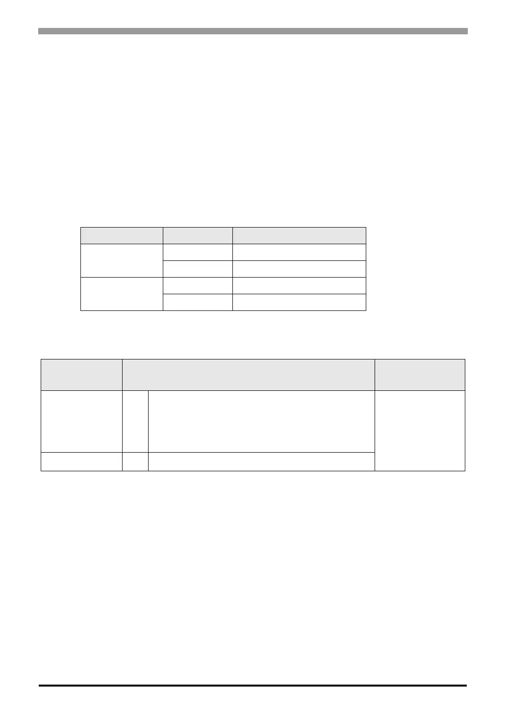
Display
(Connection Port)
Cable Remarks
GP3000 (COM1)
ST (COM1)
LT (COM1)
IPC
*1
PC/AT
*1 Available only with COM ports that support RS-232C.
) IPC COM Port (page 7)
1A User-created cable
Cable length: 15m or
less
GP-4105 (COM1) 1B User-created cable
 Loading...