118
Second
ring
CHAPTER SIX
Top
ring
I
~><:§~7::;./_
-:Oil
control
Ii ring
5. Position the piston so the numbered side
of
the rod
(Fig
ure
41) is toward the camshaft side
of
the engine. In-
sert the piston/connecting rod assembly into the cylinder
(Figu re 44).
Lightly
tap on the piston crown with a
wooden hammerhandle to insert the piston. Make sure the
rod does not bang against the crankshaft.
6. Clean the connecting rod bearings carefully, including
the back sides. Coat the crankpin journal and bearings
with clean engine oil. Place the bearings in the connecting
rod and cap.
7. Pull the connect ing rod and bearing into position
against the cran kpin. Lightly lubricate the connecting rod
bolt threads with engine oil.
8. Install the connecting rod cap. Make sure the rod and
cap areproperly aligned. Install the cap bolts finger-t ight.
9. Tighten the cap retaining bolts to speci fication (Table
4).
10. Check the connecting rod side clearance as described
under Piston/Connecting
Rod
Removal in this chapter.
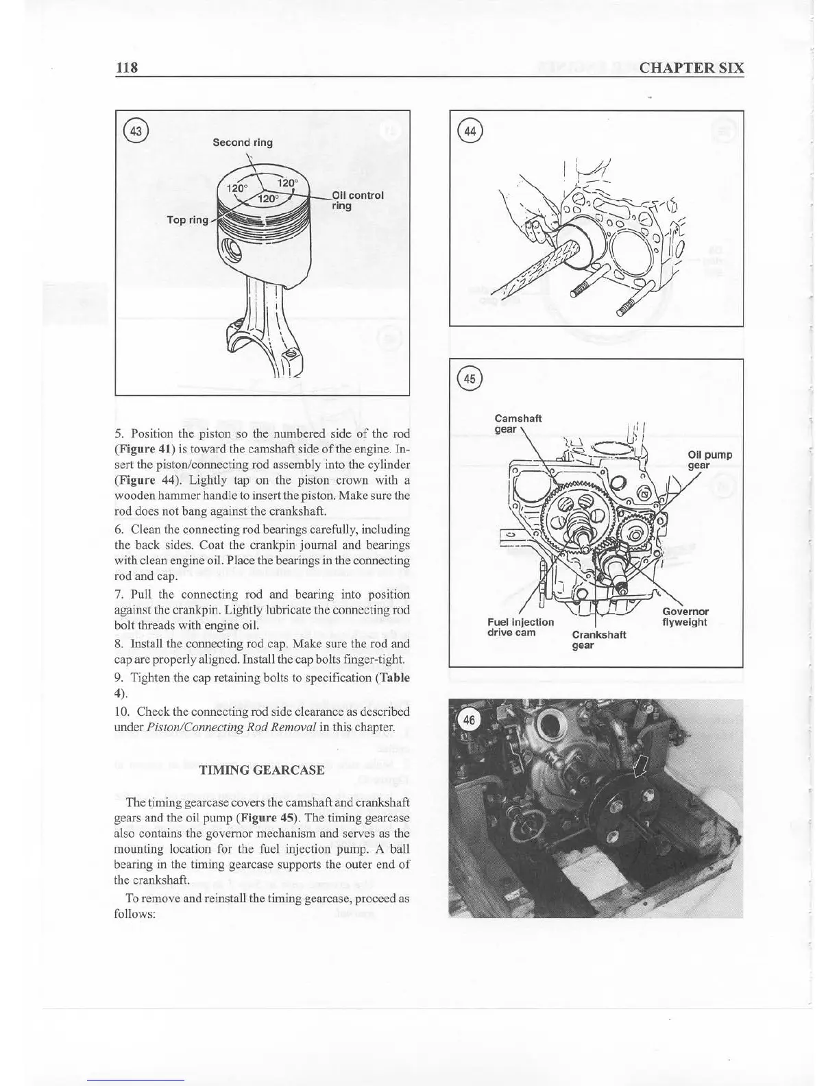
TIMING GEARCASE
The timing gearcase covers the camshaft and crankshaft
gears and the oil pump
(Figure 45). The timing gearcase
also conta ins the governor mechanism and serves as the
mounting location for the fuel injection pump.
A ball
bearing in the timing gearcase supports the outer
end
of
the crankshaft.
To
removeand reinstall the timing gcarcasc. proceedas
follows:
Cam
shaft
gear
Fuel injection
dri ve cam
Crankshaft
gear
Oil pump
gear
Governor
flyweight