166
R
emev
al/l
nst
allation
Seawater cooling system.f
The thermostat on 1GM and IGM I0 engines is located
in the cylinder head (Flgure 2). The thermostat on two-
and three-cylinder engines is located in the thermostat
housing (Figure 3 and Flgure 4).
311M
and 3HM35 en-
gines arc equipped with two thermostats (Fig
ure
4).
1. Drain the seawater from the engine as desc ribed in
Chapter
Four
.
2. Loosen the hose clamps and disconnect the hoses from
the thermostat cover
(Figure 8).
3. Remove the thermostat cover retaining bolts and
washers. R
emove
the c
over
and the gasket. Discard the
gasket.
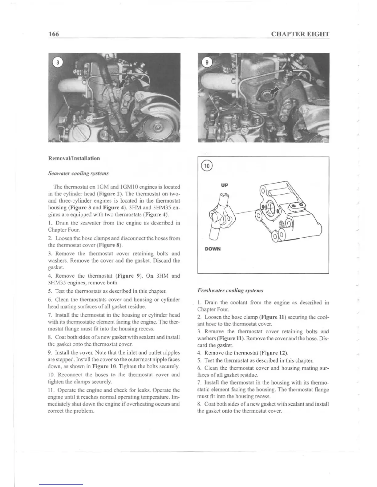
4. Remove the thermostat (Figure 9). On 3HM and
3
11
M35 engines, remove beth.
5. Test the thermostats as described in this chapter.
6. Clean the thermostats
cover
and housing
or
cylinder
head mating surfaces
of
all gasket residue.
7. Install the thermostat in the housing or cylinder head
with its thermostatic element facing the engine. The ther-
mostat flange must fit into the housing recess.
8. Coat both sides
ofa
new gasket with sealant and insta ll
the gasket onto the thermostat cover.
9. Install the cover. Note that the inlet and outlet nipples
arc stepped. Install the cove r so the outermost nipple faces
down, as shown in
Ftgur
c 10. Tighten the bolts securely.
10. Reconnect the hoses to the thermostat cover and
tighten the clamps securely.
11. Operate the engine and check for leaks. Operate the
engine until it reaches normal operating temperature. Im-
mediately shut down the engine
if
overheatingoccurs and
correct the problem.
CHAPTER EIGHT
DOWN
Freshwater cooling systems
I. Drain the coolant from the engine as described in
Chap
ter Four.
2. Loosen the hose clamp (Ffgure II ) securing the cool-
anthosclothethermostateove~
3. Remove the thermostat cover retaining bolts and
washe
rs(
F
i
g
u
~
II
). Remove the cover and the hose. Dis-
card the gasket.
4. Remove the thermostat (Figure 12).
5. Test the thermostat as described in this chapter.
6. Clean the thermostat c
ove
r and housing mating sur-
faces of all gasket residue.
7. Install the thermostat in the housing with its thermo-
static element facing the housing. The thermostat flange
must fit into the housing recess.
8. Coat both sides
of
a new gas ket with sea lant and install
the gasket onto the thermostat cover.