E
LEC
TRICAL SYSTEM
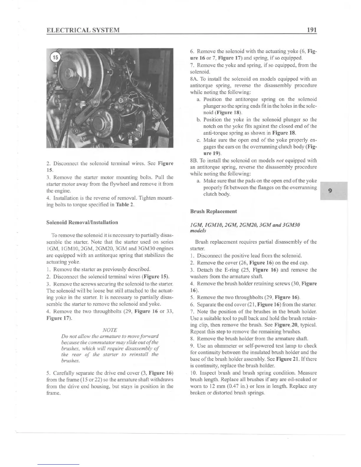
2. Disconnect the solenoid terminal wires. See Fig
ure
15.
J. Remove the starter motor mounting bolts. Pull the
starter motor away from the flywheel and remove it from
the engine.
4. Installation is the
reverse
of
removal. Tighten mount-
ing bolts to torque specified in Tab le 2.
Solenoid Removal/Ins
talla
tio n
To remove the solenoid it is necessary to partially disas-
semble the starter. Note that the starter used on series
10 M, lGM I
O,
2GM . 2GM20. JGM and 3GM3
0cn
gines
arc equipped with an antitorquc spring that stabilizes the
actuating yoke.
I. Remove the starter as previously described.
2. Disconnect the solenoid term inal wires (Figure 15).
3. Remove the screws securing the solenoid to the starter.
The solenoid will
be loose but still attached to the actuat-
ing yoke in the starter.
It is necessary to partially disas-
semble the starter to remove the solenoid and yoke.
4. Remove the
1\\'0
throughbolts (29. f igure 16 or 33,
Ftg
ur
e 17).
NOTE
Do not allow
the
armature to
move
forward
because
the
commutator may slide
out
of
the
brushes, which will require disassembly
of
the rear
of
the starter to reins tall the
brushes.
5.
Caref
ully separa te the drive end c
ove
r (3.
fi
gur
e 16)
from the frame ( 15or 22) so the armature shaft withdraws
from the drive end housing, but stays in position in the
frame.
191
6. Remove the solenoid with the actuating yoke (6, f ig-
ur
e 16 or 7,
Figur
e 17) and spring.
if
so equipped.
7. Remove the yoke and spring,
if
so equipped. from the
solenoid.
8A. To install the solenoid on models equipped
with an
antitorque spring. reverse the disassembly procedure
while noting the following:
a. Position the antito rque spring on the solenoid
plunger so the spring ends fit in the holes in the sole-
noid (f igure 18).
b. Position the yoke in the solenoid plunger so the
notch on the yoke fits against the closed end
of
the
anti-torque spring as shown in
Figure
18.
c. Make sure the open end
of
the yoke properly en-
gages the cars on the overrunning clutch body
(Fig-
ure
19).
8B. To install the solenoid on models
not
equipped with
an antitorquc spring, reverse the disassembl y procedure
while noting the following:
a. Make sure that the pads on the open
end
of the yoke
properly fit between the flanges on the overrunning
clutch
body
.
Bru sh Repl acem ent
IG.\I.
IG
,\l10
. 1G
.\I
. 1G.\110.
3G
.
\I
and
3G
.\l
30
mod
els
Brush replacement requires partial disassembly of the
starter.
1. Disconnect the positive lead from the solenoid.
2. Remove the cover (26,
fi
gure
16) on the end cap.
3. Detach the E-ring (25, Figure 16) and remove the
washers from the armature shaft.
4. Remove the brush holder retaining screws (30,
Figure
16).
5. Remove the two throughbolts (29.
Figure
16).
6. Separate the end cover (21,
Fi
gure
16) from the starter.
7. Note the position
of
the brushes in the brush holder.
Use a suitable tool to pull back and hold the brush retain-
ing clip. then remove the brush. See
figur
e 20, typical.
Repeat this step to remove the remaining
brushes.
8. Remove the brush holder from the armature shaft.
9. Use an ohmmeter
or
self-powered test lamp to check
for continuity between the insulated brush holder and the
base
of
the brush holder assembly. See
fi
gure
21. If there
is continuity. replace the brush holder.
10. Inspect brush and brush spring condition. Measure
brush length. Replace all brushes if any are oil-soaked or
worn to 12 mm (0.47
in.) or less in length. Replace any
broken or distorted brush springs.
9