TRANSMISSION-KBW SERIES
9. Referto Steps 7 and 8
and
disassemble the clutch com-
ponents on the reverse gear.
10.
Lay
the shift ring and pressure plate assembly flat.
11. Remove the pressure plate return springs (24,
Figure
3), then lift
off
the top pressure plate (17)
and
remove the
steel balls (18).
12. Liftthe shiftring (25,
Figure3)
and
driving plate(22)
off
the bottom pressure plate and remove the three re-
maining balls.
13. Slip the shift ring (25,
Figure 3)
off
the driving plate
(22).
14. Remove the alignment pins (21,
Figure 3)
and
detent
pins (20) with springs (19) from the driving plate (22).
Inspection
I.
Check
the
gear
teeth for excessive wear, corrosion or
rust and mechanical damage.
Check
the teeth for galling,
chips, cracks, missing pieces, distortion or discoloration
from overheating.
Check
the splines for excessive
wear
or
damage. Replace the gears
if
damaged.
221
2. Inspect the output shaft bearings
and
seal surfaces for
excessive wear, grooving, metal transfer and discolor-
ation from overheating.
3. Inspect the key and output shaft keyway for damage.
NOTE
Shims behind the outer bearing race in the
mountingflange determine bearingpreload
for
the outputshaft bearings. Save the shims
and
reinstall them
if
reusing the original
parts.
4. Inspect the input shaft bearing outer races in the trans-
mission case and mounting flange.
If
either race is dam-
aged
or excessively worn, remove it using a suitable
puller.
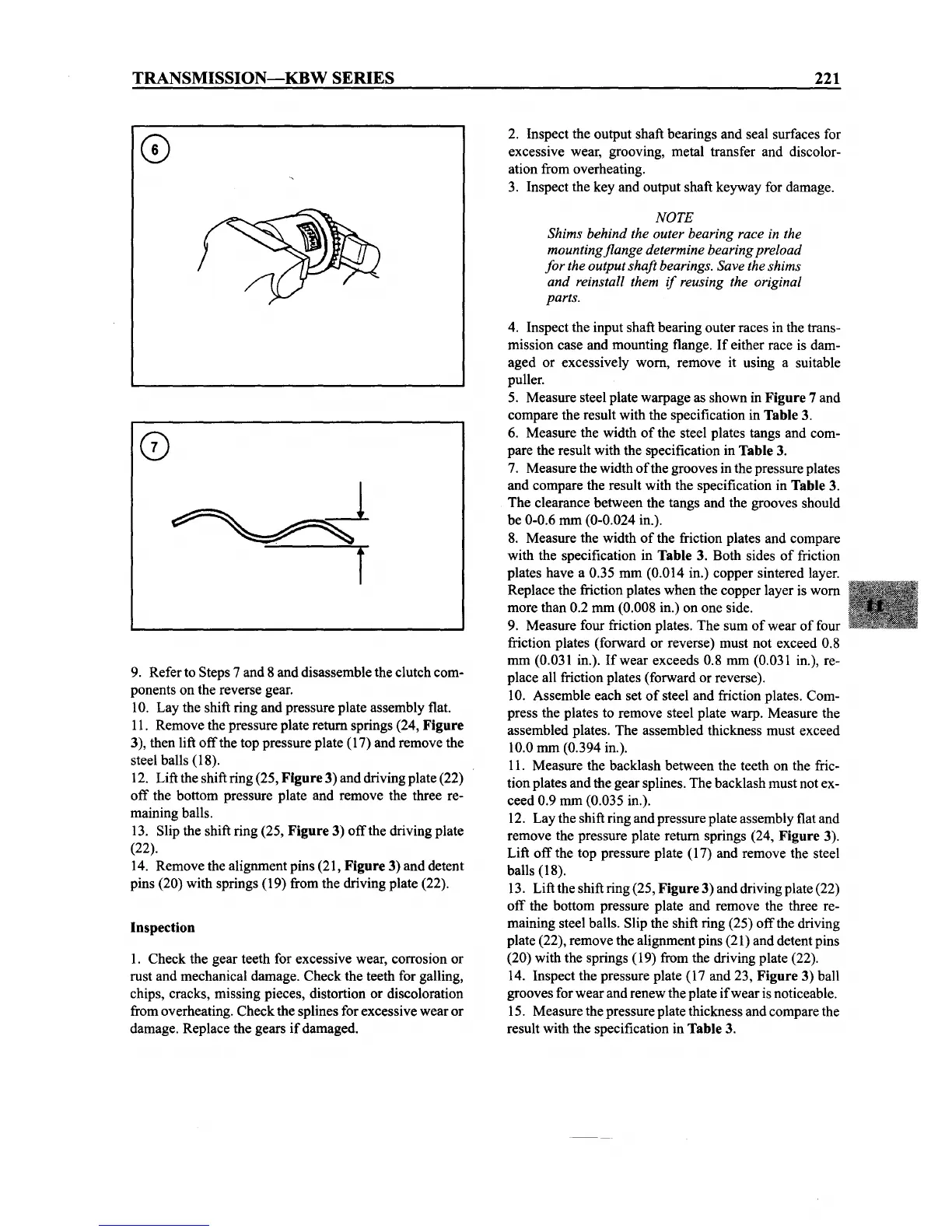
5. Measure steel plate warpage as shown in
Figure 7 and
compare the result with the specification in
Table3.
6. Measure the width
of
the steel plates tangs
and
com-
pare the result with the specification in
Table3.
7. Measure the width
of
the grooves in the pressure plates
and
compare the result with the specification in Table3.
The
clearance between the tangs and the grooves should
be 0-0.6 rom (0-0.024 in.).
8. Measure the width
of
the friction plates and compare
with the specification in
Table 3. Both sides
of
friction
plates have a 0.35
mm
(0.014 in.) copper sintered layer.
Replace the friction plates
when
the copper layer is
worn
more than 0.2 rom (0.008 in.) on one side.
9. Measure four friction plates.
The
sum
of
wear
of
four
friction plates (forward or reverse)
must
not exceed 0.8
mm (0.031 in.).
If
wear
exceeds 0.8 rom (0.031 in.), re-
place all friction plates (forward or reverse).
10. Assemble each set
of
steel and friction plates. Com-
press the plates to remove steel plate warp. Measure the
assembled plates.
The
assembled thickness
must
exceed
10.0
mm
(0.394 in.).
11. Measure the backlash between the teeth on the fric-
tionplates
and
the
gear
splines.
The
backlash
must
not ex-
ceed
0.9 mm (0.035 in.).
12.
Lay
the shift ring and pressure plate assembly flat and
remove the pressure plate return springs (24,
Figure 3).
Lift
off
the top pressure plate (17) and remove the steel
balls (18).
13. Liftthe shiftring (25,
Figure 3) and driving plate (22)
off
the bottom pressure plate and remove the three re-
maining steel balls. Slip the shift ring (25)
off
the driving
plate (22), remove the alignment pins (21) and detent pins
(20) with the springs (19) from the driving plate (22).
14. Inspect the pressure plate (17 and 23,
Figure 3) ball
grooves for
wear
and renew the plate
if
wear
is noticeable.
15. Measure the pressureplate thickness and compare the
result with the specification in
Table3.