SINGLE-CYLINDER ENGINES
93
/
- Dial gauge
,
3. Check all journals aga inst specifications (Table 1) for
out-of-roundness and taper. Have the crankshaft
reground, ifnecessary, and install
new
undersize bearings.
5
If gear back lash is incorrect, rep lace the camshaft
and crankshaft gears.
Inspection
1. Clean the crankshaft thoroughly with solvent. Blow
out the oil passages with compressed air.
2. Check the main and connecting rod
journa
ls for
wea
r,
scratches, grooves, scoring or cracks. Check the oil seal
contact surface for burrs, nicks or other sharp edges that
might damage a seal during installation.
NOTE
Unless precision measuring equipment is
available, have a machine shop perform
Step 3.
MAI N BE
ARING
S
The crankshaft is supported at each end by bush-
ing-type main bearings.
The
front main beari ng is located
in the crankcase and the rear main bearing is located in the
removable main bearing carrier. Thrust bearings located
at the front
of
the crankshaft control crankshaft end play.
Refer to
Figure
70.
Remove the crankshaft as described in the previous sec-
tion for access to the main bearings and thrust washers.
Unless prec ision measuring equipment is available, have
a dealership or machine shop measure main bearing di-
mensions. Refe r to specifications in
Table I.
If bearing replacement is necessary, have the main bear-
ings replaced by a dealership or machine shop. Make sure
the oil holes
(B, Fi
gur
e 76) in the main
bea
rings align
with the oil passages in the crankcase and main bearing
earner.
CA
MS
HAF
T
Removal
and
Installation
I. Remove the fuel transfer
pump
(F
igure 80).
2. Remove {he crankshaft as previously described.
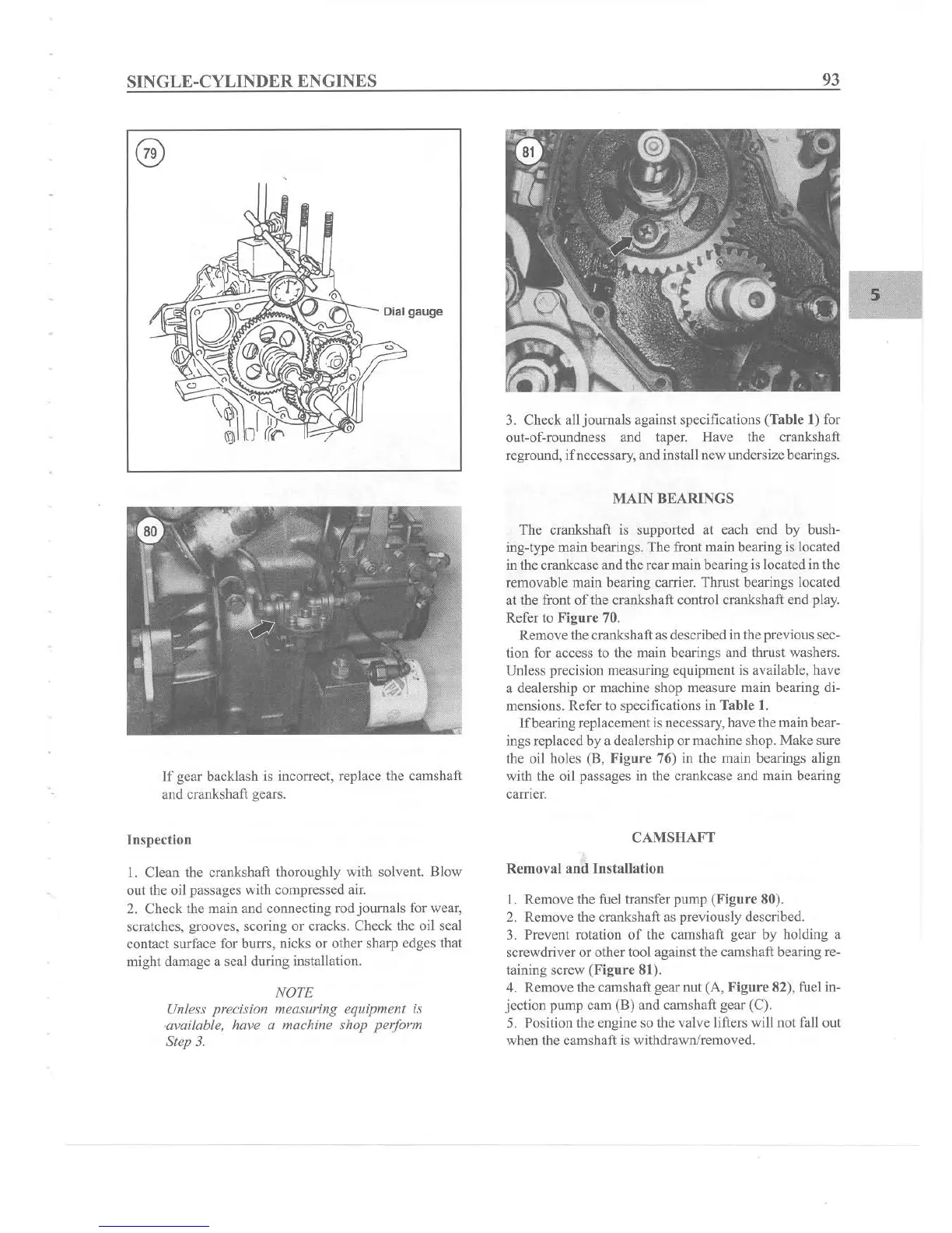
3. Prevent rotation
of
the camshaft gear by holding a
screwdriver or
other
tool against the
cams
haft bearing re-
taining screw (F igu
re
81).
4. Remove the camshaft gear nut (A, Flgure 82), fuel in-
jection
pump
cam (B) and camshaft gear (C).
5. Position the engine so the valve lifters will not fall out
when the camshaft is withdrawn/removed.