92
B
A
d. Position the new seal in the housing recess with its
open end facing the inside
of
the bearing hous ing.
Drive the seal into place
with a suitably sized seal
driver.
II.
Refer to Main Bearings for information con cern ing
inspection
of
the main bearings and thrust bearings.
12. Reinstall the crankshaft by reversing the removal
procedure white noting the followi ng:
a. Thoroughly lubricate the main bearings and thrust
bearings.
b. Install the inner, front thrust bearing so the oil
grooves arc
toward the inside
of
the crankcase and
the tab fils into the recess (Fig
ur
e 75) in the cran k-
case. Apply a light coating
of
grease to hold the
thrust bearing in place.
c. Install a new O-ring (A, Figure 76) on the main
bearing housing.
d. Tighten the main bearing housing bolts to the torque
specified in Table 2.
e. Install the outer front thrust bearing so the oil
grooves (A,
Figur
e 77) are toward the outside
oft
he
crankcase
and
the tab (B) fits onto the pin in the
crankcase.
f. Install the thrust washer (Figure 73) so the beveled
side
of
the inner hole is toward the crankcase.
-----
CHAPTER
FIVE
Cam shaft
gear
g. Measure crankshaft end play by inserting a feeler
gauge between the crankshaft main journal and the
inner thrust bearing, or by installing a dial gauge
that measures fore and aft movement of the fly-
wheel or crankshaft. Using a large screwdriver,
force the crankshaft back and forth. Measure crank-
shaft end play and compare the measurement with
the specification in Ta ble 1. Replace the inner thrust
bearing to obtain the des ired end play.
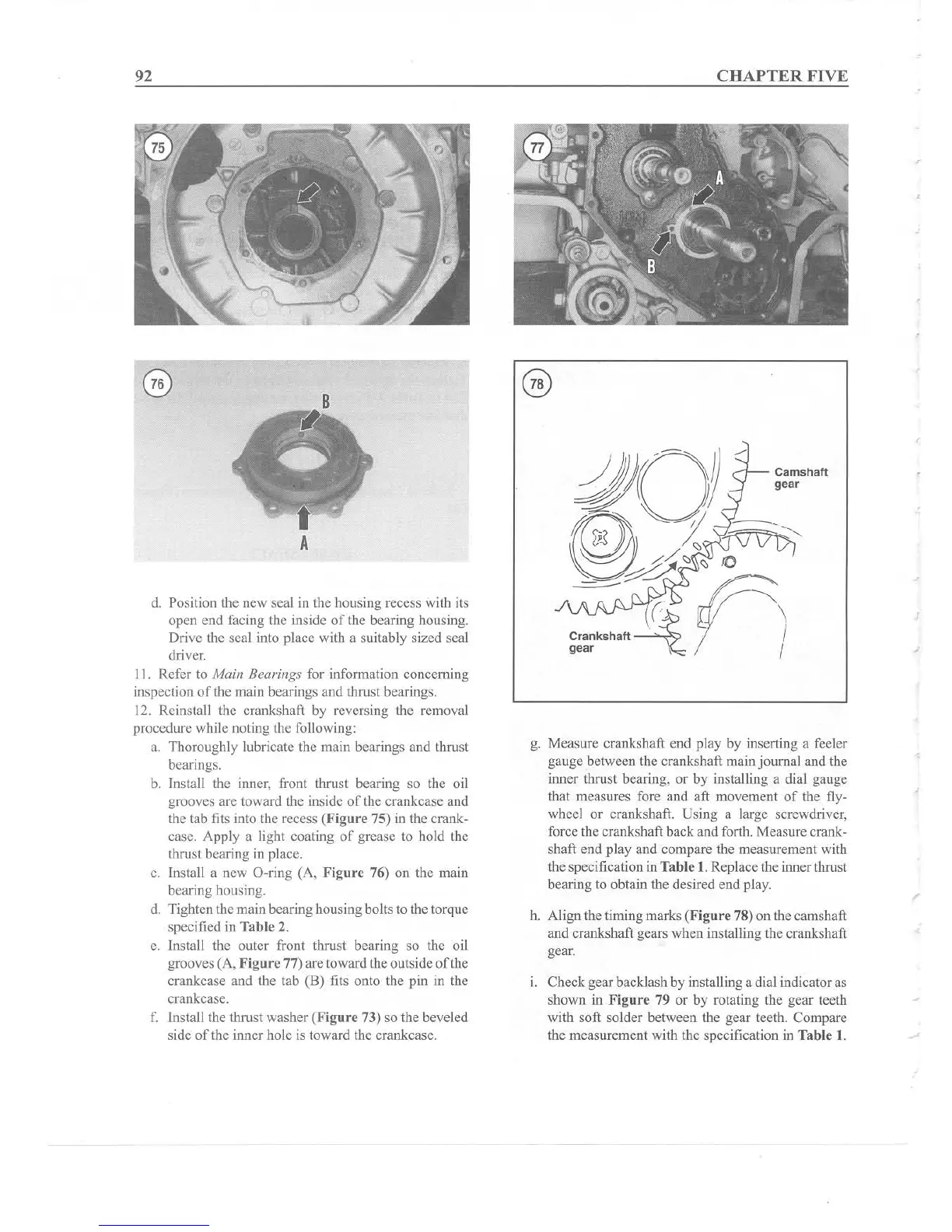
h. Align the timing marks
(Figure 78) on the camshaft
and crankshaft gears when installing the crankshaft
gear.
l. Check gear backlash by installing a dial indicator as
shown in Figure 79 or by rotating the gear teeth
with soft solder between the gear teeth. Compare
the measurement with the specification in Table
I.