SINGLE-CYLI
ND
ER
ENGINES
91
3. Remove the drive disc (Figure 68).
4. Gradually loosen and remove the flywheel bolts,
working in a diagonal pattern. Install two drive disc bolts
into two outer holes in the flywheel
(Figur
e 69), then use
the screws to pull and remove the flywheel.
5. Inspect the ring gear. If the ring gear is excessively
worn or damaged, usc the following procedure to remove
the ring gear:
a. Heat the ring gear evenly, then drive the ring gear
off
the flywhee l.
b. Heal the ring gear prior to installation. Drive the
ring gear onto the flywheel, being careful not to
damage the g
ear
teeth.
6. Reverse the removal procedure to install the flywheel.
Tighten the flywheel retaining bolts to the torque speci-
fied in Table 2. Refer to Chapter Ten to install the drive
disc and transmission.
DRIVE
DISC
Refer to Chapter Ten for drive disc procedures (Figure
68).
CRANKSHA
FT
Removal and Installation
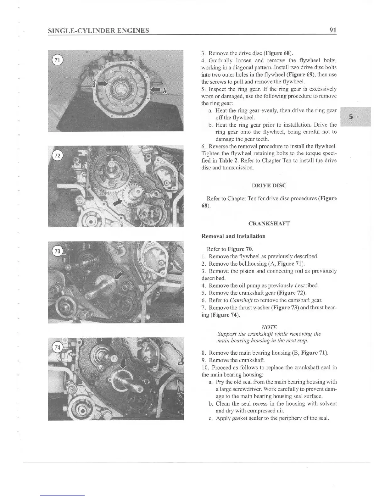
Refer to Figure 70.
1. Remove the flywheel as previously described.
2. Remove the bellhousing (A, Fig
ure
71).
3. Remove the piston and connecting rod as previously
described.
4. Remove the oil pump as previously described.
5. Remove the crankshaft gear (Figure 72).
6. Refer to Camshaft to remove the camshaft gear.
7. Remove the thrust washer (Fig
ure
73) and thrust bear-
ing
(Figur
e 74).
NOTE
Support the crankshaft while removing the
main bearing housing in the next step.
8. Remove the main bearing housing (8, Fig
ure
71).
9. Remove the crankshaft.
10. Proceed as follows to replace the crankshaft seal in
the main bearing housing:
a. Pry the old seal from the main bearing housing with
a large screwdriver. Work carefully to prevent dam-
age to the main bearing housing seal su
rf
ace.
b. Clean the seal recess in the housing with solvent
and dry with compressed air.
c. Apply gasket sealer to the periphery
of
the seal.
5