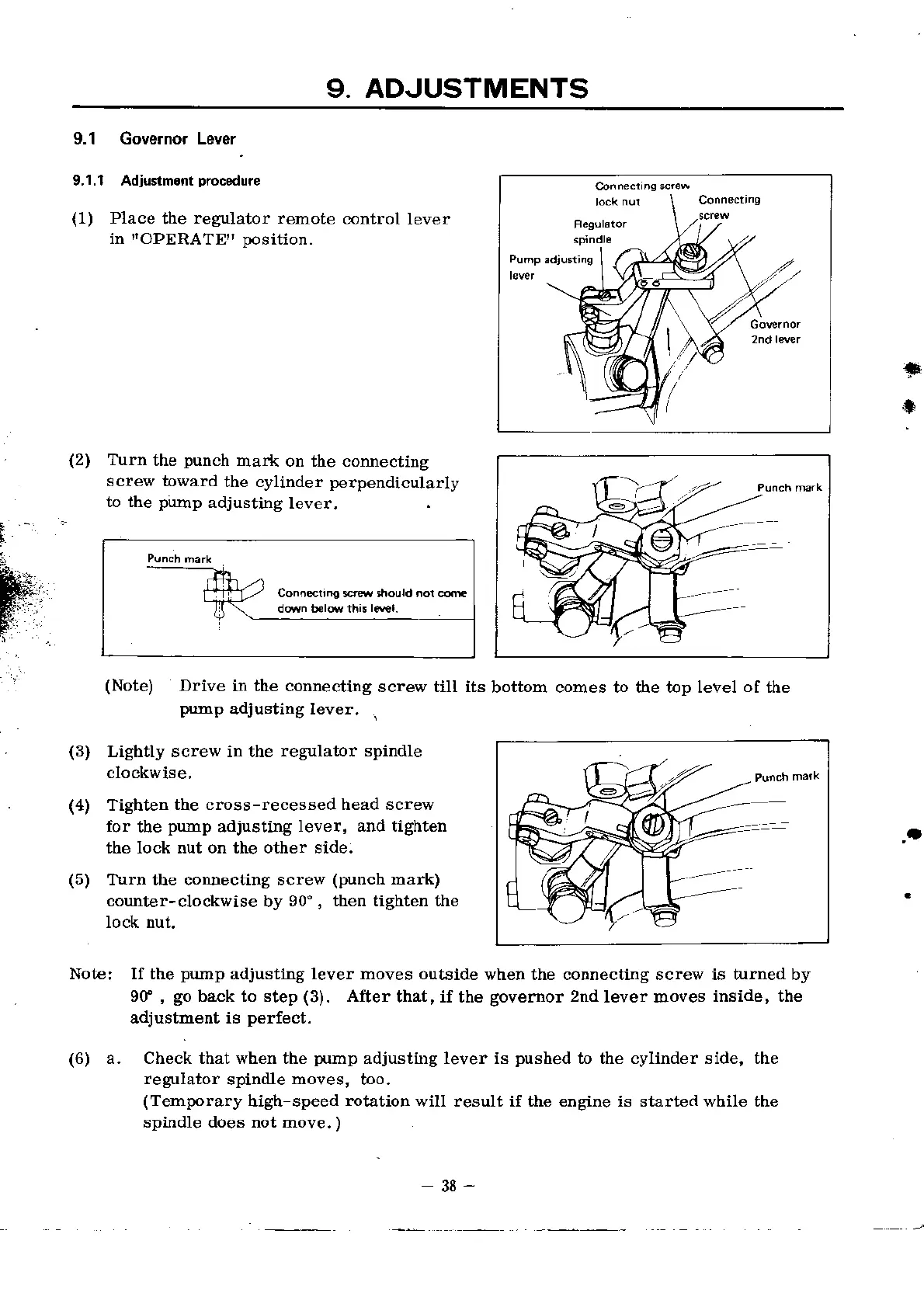
9. ADJUSTMENTS
9.1 Gove.nor Lever
_
9.1.1 Adjustm.nrprocedure
(1)
Place
the
regulator remote
clontrol
lever
in
IiOPERATE'
position.
(2)
Turn
the
punch
mar.k on the connecting
screw toward
the cylinder
perpendicularly
to the
pump
adjusting
levea,
*
*
(Note)
Drive
in the connecting
screw till its
bottom comes to the top level
of
the
pump
adJusting lever.
a
(3)
(4)
(s)
Lightly screw in the
regulator spindle
clockwise,
Tighten
the cross-recessed head screw
for
ttre
pump
adiusting
lever, a$d tighten
the lock nut on the other side.
I\rrn the corulecting screw
(punch
mart)
counter-clockwise
by
90', then tighten the
lock nut.
(6) a. Check tbat when the
p{rmp
adjustiDg lever is
pushed
to the
regulator
spindle
moves,
boo,
(Temporary
high-speed
rotation
will result if the entsine is
sDindle does not move.
)
Note: If the
pump
adiusting lever moves outside
when the connecting screw is hrned by
9f
,
go
back to step
(3).
After
that, if the
governor
2nd
lever moves
inside, the
adiustment is
perfect.
cylinder side, the
started while the
Conn@.n! s* stould .or .dn