After
reassembly
is completed,
check,
injection noise is nonnal.
9.1.2 Readiunmentproc€duro
Although the
above steps
followed
for simplicity'3
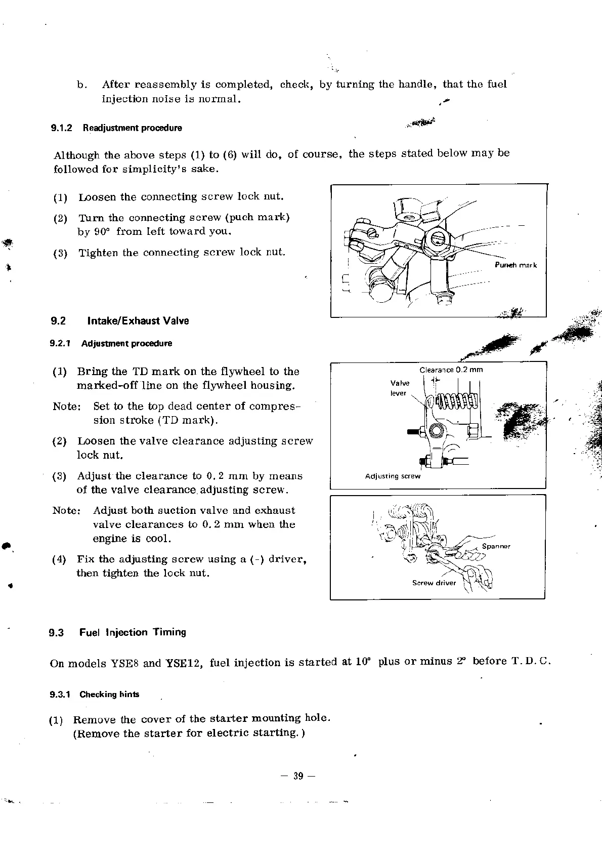
Inosen
the connecting
screw lock
nut.
Turn
the connecting
screw
(puch mark)
by 90"
fr:om left toward
you.
Tighten
the connecting
screw
lock nut.
9.2 Intake/ExhaunValve
9.2.1
Adjuitmertproc€dure
(1)
Brtng the TD mark on the fl''wheel to the
mar*ed-off Iine
on
the flywheel
housing,
Note: Set to the top
dead center of
compres-
sion stroke
(TD
mark).
(2)
Inosen the valve clearance adjusting screw
lock nut,
(3)
Adjust the clearance to 0.2 mm by means
of
the valve
clearance
adjustitrg screvr.
Note:
Adjust
both suction valve and exhaust
valve clearances to
0. 2 mm whe[
the
engine is cool.
(4)
Fix the adjusting screw using a (-) driver,
then tighten the lock
nut.
9.3
Fuel Iniection
Timing
6u h'rnind fha hrndlo th.r fho fr'ol
b.
(1)
to
(6) will do, of course,
the steps
sLlted below
may be
sake.
(1)
12)
'4r
l
(3)
a
on models YSES and YSE12,
9.3.1 Ch€cking
hints
(1)
Remove the
cover
of the
(Remove the starter
for
fuel injection
is
started
at lf
plus
or minus
t
before
T. D. C
starter mountiog
hole.
electdc
starting.
)
\l
'.--Fi
:)
39
 Loading...