3 Electrical Installation
YASKAWA ELECTRIC
TOEP C710606 15E - AC Drive V1000 - Quick Start Guide
EN 19
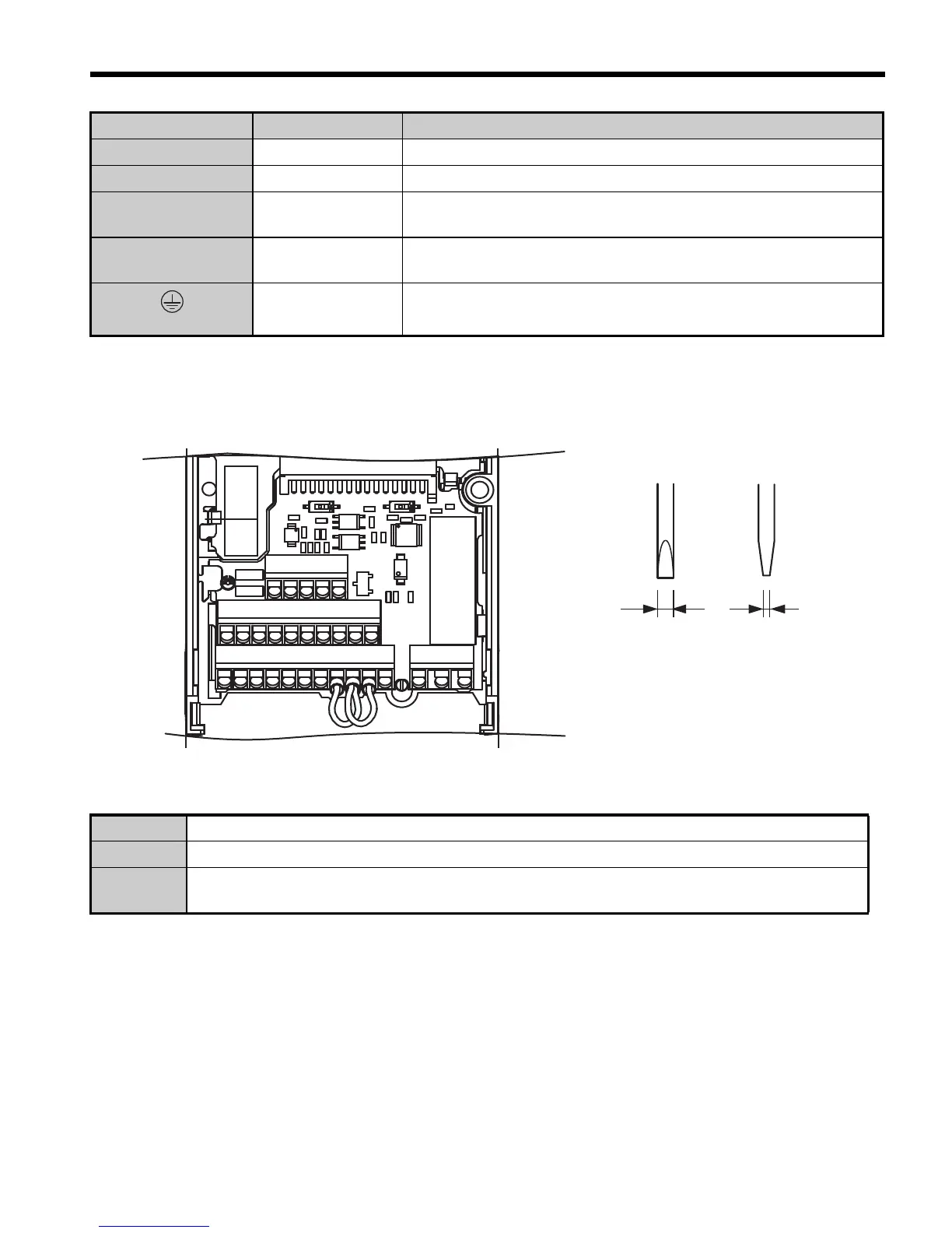
Control Circuit Terminals
The figure below shows the control circuit terminal arrangement. The drive is equipped with
screwless terminals.
There are three DIP switches, S1 to S3, located on the terminal board.
U/T1, V/T2, W/T3 Drive output Connects to the motor.
B1, B2 Braking resistor For connecting a braking resistor or the braking resistor unit option.
+1, +2
DC reactor
connection
Linked at shipment. Remove the link to install a DC choke.
+1, –
DC power supply
input
For connecting a DC power supply.
(2 terminals)
Ground Terminal
For 200 V class: Ground with 100 or less
For 400 V class: Ground with 10 or less
SW1 Switches analog input A2 between voltage and current input.
SW2 Enables or disables the internal RS422/485 comm. port terminal resistance.
SW3
Used to select sourcing (PNP)/sinking (NPN, default) mode for the digital inputs (PNP requires
external 24 Vdc power supply).
Terminal Type Function
S1 S2 S3 S4 S5 S6 SC HC H1 H2 RP
R+
R- S+ S-
IG
P1 P2 PC A1 A2 +V AC AM AC MP
MA MB MC
S1
S2
S3
Use a straght-edge screwdriver
with a blade width of max 2.5 mm
and a thickness of max 0.6 mm to
release the terminals
 Loading...


