16
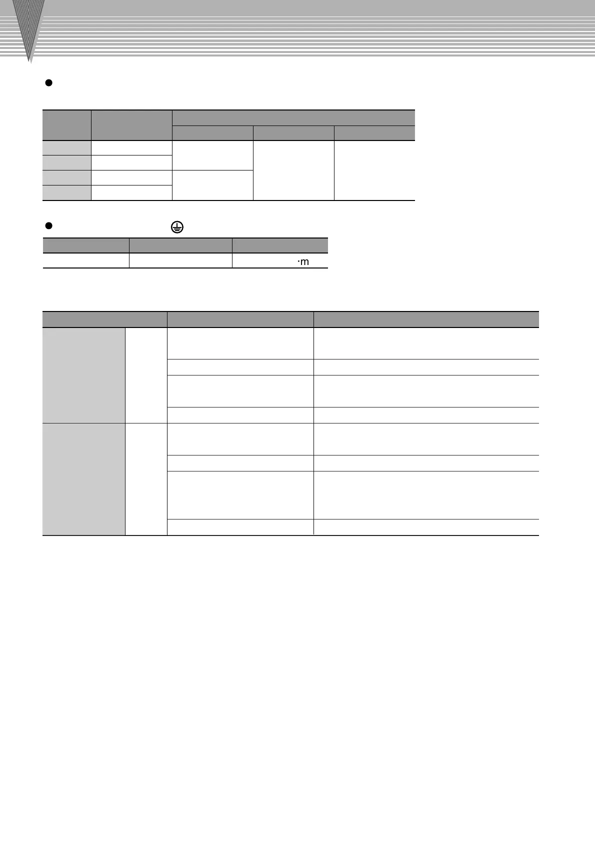
Capacity
W
SERVOPACK
Type
Terminal Symbol
100
200
400
750
SJDE-01A
SJDE-02A
SJDE-04A
SJDE-08A
L1, L2
HIV1.25mm
2
HIV1.25mm
2
Wiring length:
20 m max.
HIV1.25mm
2
Wiring length:
0.5 m max.
HIV2.0mm
2
M4 1.2 to 1.4N
m
U, V, W +, –
Connector Name and Symbol
I/O signal
connector
Encoder signal
connector
Item Specifications
Wire Size Terminal Screw Size Tightening Torque
HIV 2.0 mm
2
min.
<Signal Line Wire Sizes>
The following wires are used for the CN1 and CN2 connectors on the SERVOPACK.
CN2
CN1
Connection Diagram
Connection Diagram
Power Supply Input Terminals (L1, L2), Motor Connection Terminals (U, V, W),
and Regenerative Unit Connection Terminals (+, –)
Ground Terminal ( )
Note
:
Connectors are used for all wiring.
Use twisted-pair wires or shielded twisted-pair
wires.
3m
AWG24(0.2 mm
2
), AWG26(0.12 mm
2
),
AWG28(0.08 mm
2
)
8 mm dia. max.
Use the cables specified by Yaskawa or use
shielded twisted-pair wires.
20m
AWG22 (0.33 mm
2
) and AWG26 (0.12 mm
2
)
Used AWG22 for the encoder power supply and
AWG26 for signal lines.
9 mm dia. max.
Cable
Maximum cable length
Applicable wires
Finished cable outer diameter
Cable
Maximum cable length
Applicable wires
Finished cable outer diameter

 Loading...


