7.2 Power Supply Contactor Sequence Circuit Board (JANCD-NTU01-#)
7-5
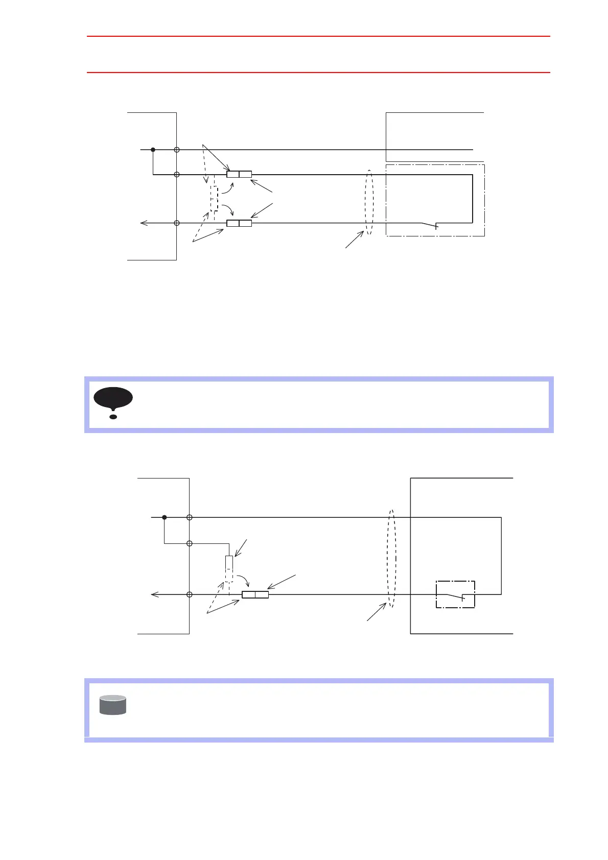
Fig. 1 Direct Connection to Tool Shock Sensor Signal Line
To connect the tool shock sensor with the cable that is built into the manipulator
1. Disconnect the minus SHOCK (-) and 24VU pin terminal from the WAGO connector,
the NTU01-CN07 power supply contactor unit.
2. Connect the minus SHOCK (-) pin terminal to the minus SHOCK (-) pin terminal of the
manipulator.
Fig. 2 Connection with Manipulator Cable
Cable that is built into the manipulator is not connected to shocks sensor because the tool
shock sensor is a option. For connecting the tool shock sensor, refer to the wiring dia-
grams in the INSTRUCTIONS for the manipulator.
When the tool shock sensor input signal is used, the stopping method of the robot can be
specified. The stopping methods are hold stop and servo power supply off. Selection of
the stopping method is set in the display of the programing pendant. For details, refer to
Explanation *1 in " 9 System Setup " of NX100 INSTRUCTIONS.
+24V!(manufactured!by!NICHIFU!Co.,!Ltd.)
PC-2005M
Manipulator!cable!(signal)
SHOCK-
PC-2005W!
(manufactured!by!NICHIFU!Co.,!Ltd.)
Shock!sensor!
(Option)
CN07
-1
-3
-4
+24V2
SHOCK
!Manipulator
PC2005W!(manufactured!
by!NICHIFU!Co.,!Ltd.)
Shock!sensor!signal!cable
Power!supply!contactor!unit
JZRCR-NTU
!!
PC-2005M!(manufactured!by!NICHIFU!Co.,!Ltd.)
+24V
PC2005M!(manufactured!
by!NICHIFU!Co.,!Ltd.)
NOTE
+24V
PC-2005M
(manufactured!by!NICHIFU!Co.,!Ltd.)
SHOCK-
PC2005M!
(manufactured!by!
NICHIFU!Co.,!Ltd.)
!Supply!cables!(PG)
SHOCK-
PC-2005W
(manufactured!by!NICHIFU!Co.,!Ltd.)
Shock!sensor!
(Option)
Use!the!manipulator!cable
CN07
-1
-3
-4
+24V2
SHOCK
!Manipulator
Power!supply!contactor!unit!
JZRCR-NTU!!
SUPPLE
-MENT

 Loading...


