7.2 Power Supply Contactor Sequence Circuit Board (JANCD-NTU01-# )
7-6
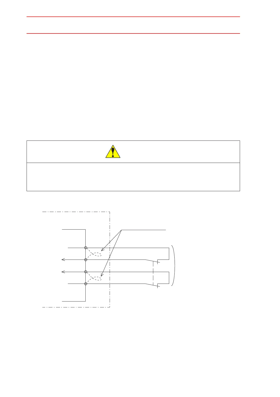
" Connection for External Axis Overrun (EXOT)
With a unit of standard specifications without an external axis, the external axis overrun input
signal is not used. In this case, a jumper cable is connected as shown in the following figure.
If an overrun input signal for an axis other than manipulator axes, for example the external
axis, is required, connect the signal input circuit in the following manner.
For safe reason, a dual circuits are used for the external axis overrun signal input. Connect
the external axis overrun signal so that both input signals are turned ON or OFF at the same
time. If only one signal is turned ON, an alarm occurs.
1. Remove the jumper cable between the connectors CN06-5 and -6 and between the
connectors CN06-7 and -8 of the JZRCR-NTU##-# power supply contactor unit.
2. Connect the external axis overrun wiring between the connectors CN06-5 and -6 and
between the connectors CN06-7 and -8 of the JZRCR-NTU##-# contactor unit.
Fig. 3 Connection for External Axis Overrun
• Remove jumper cable installed on system input signal before connect-
ing the input signal lines.
Failure to observe this caution could lead to injury or mechanical failure.
CAUTION
NX100
CN06
-5
-6
-7
-8
+24V2
EXOT1
EXOT2
024V
Remove!the!jumper!cable
Turn!ON/OFF
at!the!same!time
External!axis!overrun
Power!supply!contactor!unit!
JZRCR-NTU!!

 Loading...


