5. PRECAUTIONS FOR INSTALLING SERVO UNIT
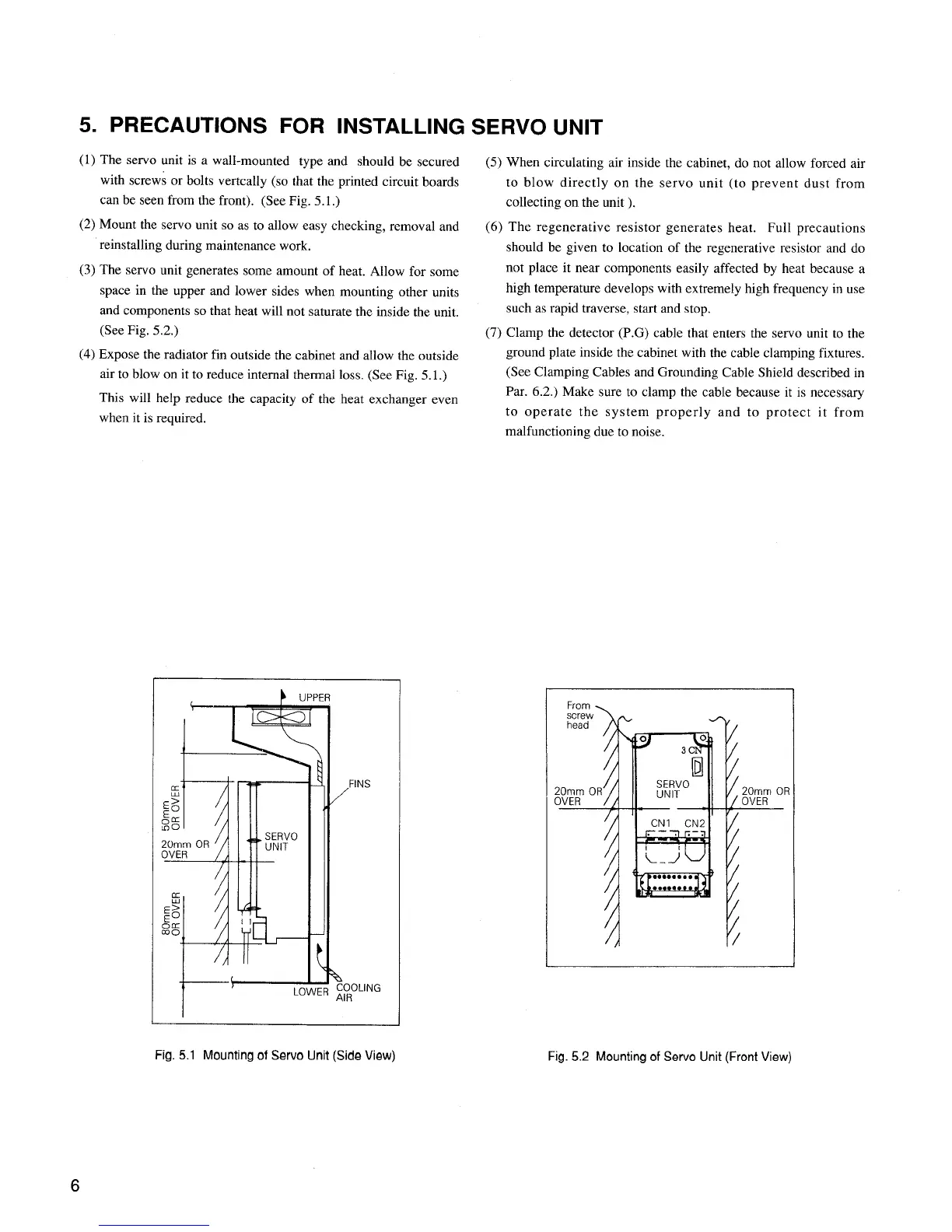
(1) The servo unit is a wall-mounted type and should be secured
with screws or bolts vertcally (so that the printed circuit boards
can be seen from the front). (See Fig. 5.1.)
(2) Mount the servo unit so as to allow easy checking, removal and
reinstalling during maintenance work.
(3) The servo unit generates some amount of heat. A11ow for some
space in the upper and lower sides when mounting other units
and components so that heat will not saturate the inside the unit.
(See Fig. 5.2.)
(4) Expose the radiator fin outside the cabinet and allow the outside
air to blow on it to reduce internal thermal loss. (See Fig. 5.1.)
This will help reduce the capacity of the heat exchanger even
when it is required.
(5) When circulating air inside the cabinet, do not allow forced air
to blow directly on the servo unit (to prevent dust from
collecting on the unit ).
(6) The regenerative resistor generates heat. Full precautions
should be given to location of the regenerative resistor and do
not place it near components easily affected by heat because a
high temperature develops with extremely high frequency in use
such as rapid traverse, start and stop.
(7) Clamp the detector (P.G) cable that enters the servo unit to the
ground plate inside the cabinet with the cable clamping fixtures.
(See Clamping Cables and Grounding Cable Shield described in
Par. 6.2.) Make sure to clamp the cable because it is necessary
to operate the system properly and to protect it from
malfunctioning due to noise.
s
ING
Fig. 5.1 Mounting of Servo Unit (Side View)
From .
R
Fig. 5.2 Mounting of Servo Unit (Front View)
 Loading...


