IM 01E21A21-02EN
<1. INTRODUCTION>
4
2. Safety Instrumented Systems
Installation
WARNING
The contents are cited from exida.com safety manual on this product specically observed for its safety
purpose. When using this product for Safety Instrumented System (SIS) application, the instructions and
procedures on this chapter must be strictly followed in order to preserve this product for that safety level.
2.1 Scope and Purpose
This chapter provides an overview of the user responsibilities for installation and operation of this product in
order to maintain the designed safety level for SIS applications.
This chapter is described proof test, repair and replacement of the transmitter, reliability data, lifetime,
environmental and application limits, and parameter settings. Functional safety is targeted for S1.01 hardware
revision, R2.02 main board software revision, R1.02 sensor board software revision and /SL option.
2.2 Using this product for an SIS Application
2.2.1 Safety Function
This product is used as a Type B of Low demand mode in the SIS application.
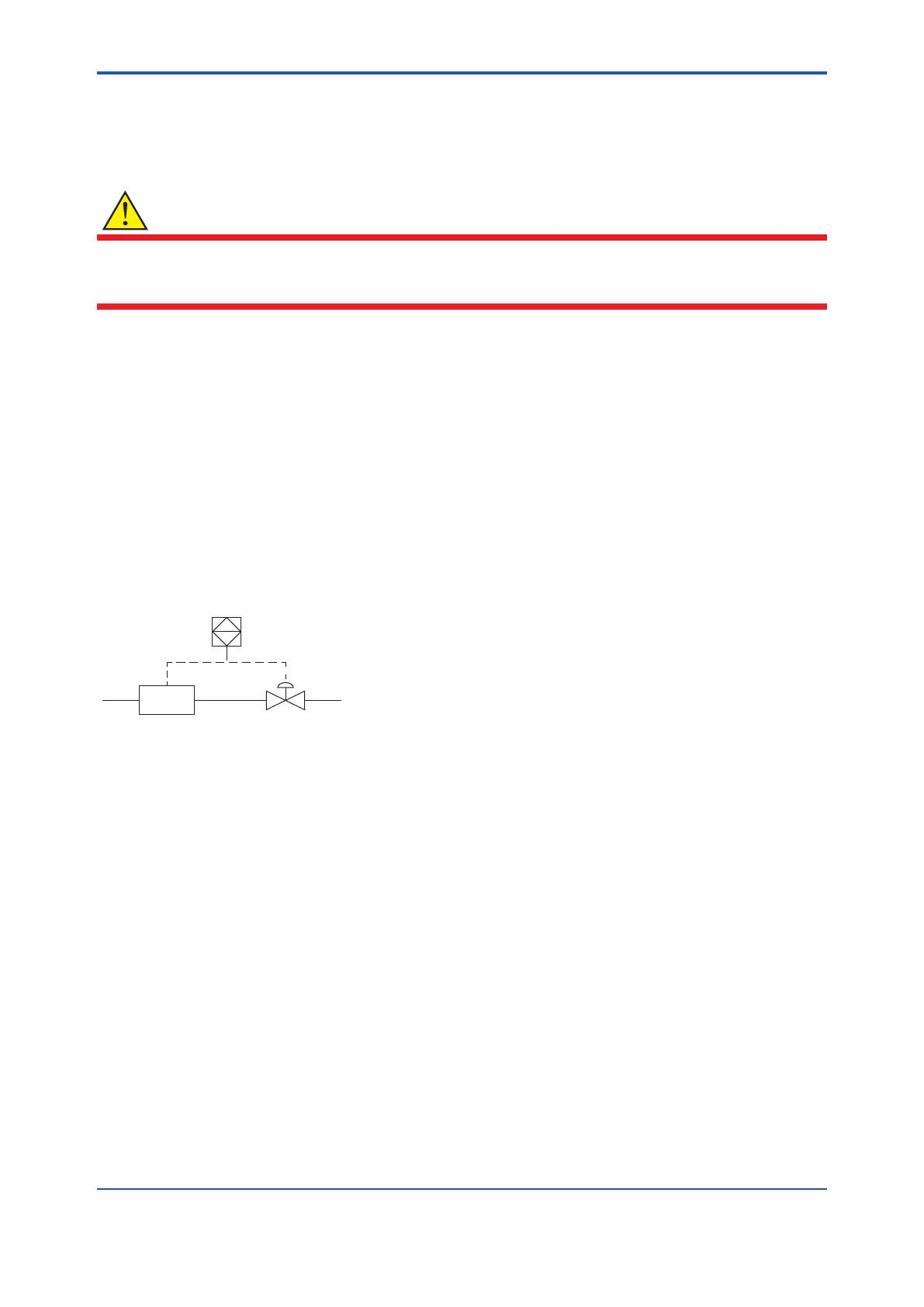
F
Safety PLC
Measuring
Device
Actuator
This product converts Flow velocity, Volume ow, Mass ow, and Flow noise (for AXG only) to current. And it
outputs “Analog Output 1” at “I/O 1” terminal as its safety functions. Other functions (display, etc…) are out of
its scope. Use this “Analog Output 1” to connect the safety PLC when this product is used as a SIS.
It is necessary to set adequate parameters before starting to use this product as a SIS. Refer to Subsection
2.2.4 and Subsection 2.2.5 for details.
2.2.2 Safety Accuracy
This product has a specied safety accuracy of 2%. This means that the internal component failure are listed in
the device failure rate if they will cause an error of 2% or larger.
2.2.3 Diagnostic Response Time
The period of the diagnostic test on this product is 8 seconds as its maximum. This product noties the failure
to the safety PLC as its host within 1 second by outputting the burnout (safety condition) at “Analog Output 1”.
For countermeasure of its failure, read Chapter 4 in the user’s manual of applicable communication type as
listed in Table 1.1.
 Loading...

