<2. Handling Cautions>
13
IM 01C25A01-01E
Model: EJX910A-F Series Date: May 22, 2006
Rev.1: July 16, 2019 Doc. No.: I FM026-A12 P.3-3
Yokogawa Electric Corpor ation
IFM 026
FNICO Rules
The FNICO Concept allows the interconnection of nonincendive field wiring apparatus to associated
nonincendive field wiring apparatus not specifically examined in such combination. The criterion for
such interconnection is that the voltage (Vmax), the current (Imax) and the power (Pmax), which
nonincendive field wiring apparatus can receive and remain nonincendive, must be equal or greater
than the voltage (Uo, Voc or Vt), the current (Io, Isc or It) and the power (Po) which can be provided by
the associated nonincendive field wiring apparatus (supply unit). In addition the maximum
unprotected residual capacitance (Ci) and inductance (Li) of each apparatus (other than terminators)
connected to the Fieldbus must be less than or equal to 5 nF and 20 respectively.
In each N.I. Fieldbus segment only one active source, normally the associated nonincendive field
wiring apparatus, is allowed to provide the necessary power for the Fieldbus system. The allowed
voltage (Uo, Voc or Vt) of the associated nonincendive field wiring apparatus used to supply the bus
cable must be limited to the range 14 V d.c. to 17.5 V d.c. All other equipment connected to the bus
cable has to be passive, meaning that the apparatus is not allowed to provide energy to the system,
except a leakage current of 50 A for each connected device. Separately powered equipment needs
galvanic isolation to ensure the nonincendive field wiring Fieldbus circuit remains passive.
The cable used to interconnect the devices needs to comply with the following parameters:
Loop resistance R': 15....150 /km
Inductance per unit length L': 0.4....1 mH/km
Capacitance per unit length C': 45....200 nF/km C' = C' line/line + 0.5 C' line/screen, if both lines are
floating or C' = C' line/line + C'line/screen, if the screen is connected to one line.
Length of spur cable: max. 60 m
Length of trunk cable: max. 1 km in IIC and 5 km in IIB
Length of splice: max = 1 m
Terminators
At the end of each trunk cable an FM Approved line terminator with the following parameters is
suitable:
R = 90...100
d. FM Explosionproof
•
•
•
•
•
•
•
•
F0218.ai
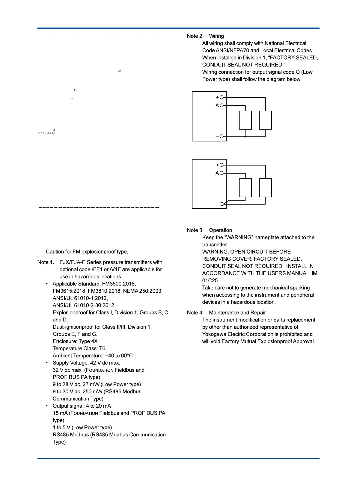
Three-Wire Connection
Pressure Transmitters
Power Supply
Voltmeter
SUPPLY
SUPPLY
+
–
+
–
Four-Wire Connection
Pressure Transmitters
Power Supply
Voltmeter
SUPPLY
SUPPLY
+
–
+
–
•
•
•