Display deviating
Quick Reference Instruction Manual
Troubleshooting
IM01U10A00-00EN-R, 2nd edition, 2017-08-29
53 / 54
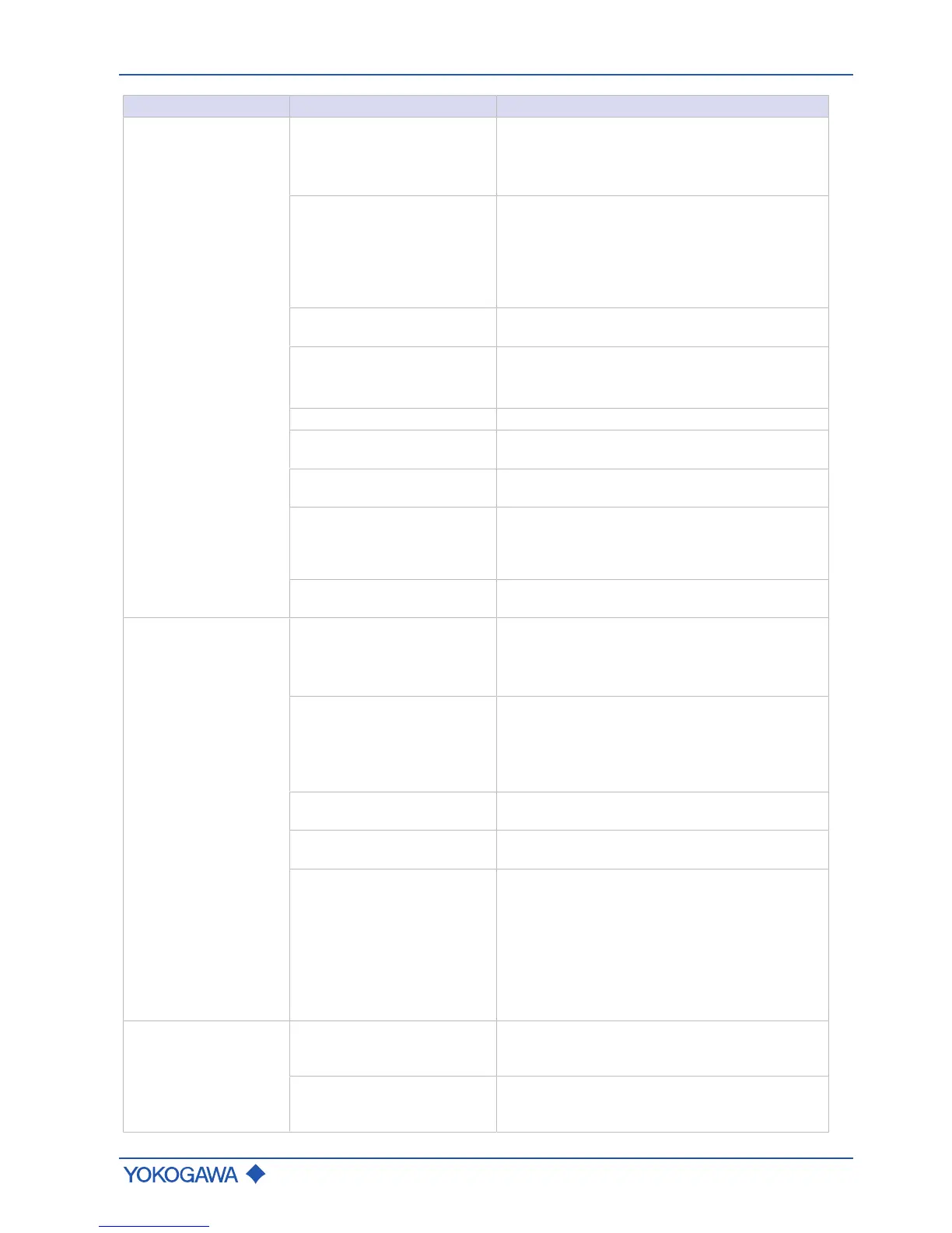
Malfunction Possible causes Remedy
Density displayed devi-
ating from actual density
Density unit, highest and low-
est value for density set incor-
rectly
– Match settings of flow meter and reading
system.
– Check LRV and URV process parameters,
see software instruction manual.
Fixed density
– Check whether the Val sel parameter is set
correctly. If a fixed value is selected, ensure
that the parameter Fix val is set correctly, see
software instruction manual.
– Set parameter Val sel to Meas val, see soft-
ware instruction manual.
Analog output trim was per-
formed incorrectly
– Correctly perform trimming, see applicable
software instruction manual.
No electrical grounding
– Ground transmitter and sensor, see [}31].
– Check correct connection of connecting cable
shield on transmitter.
Bubbles in medium
– Check pipe and installation, see [}16].
Connecting cable incorrectly
connected for remote type
– Check cable connections and correct, if
necessary, see [}33].
Faulty temperature measure-
ment
– Check temperature measurement circuits
TP1 – TP3 of connecting cable.
Corrosion and erosion
– If corrosion or erosion due to corrosive media
is suspected, contact Yokogawa and have
density and mass flow recalibrated, if neces-
sary.
Contaminated measuring
tubes
– Clean measuring tubes.
Temperature displayed
deviating from actual
temperature
Temperature unit, highest and
lowest value for temperature
set incorrectly
– Match settings of flow meter and reading
system.
– Check LRV and URV process parameters,
see applicable software instruction manual.
Non-adjustable temperature
– Check whether the Func sel parameter is set
correctly. If a fixed value is selected, ensure
that the Fix val is set correctly, see applicable
software instruction manual.
– Set parameter Func sel to Inter val.
Analog output trim was per-
formed incorrectly
– Correctly perform trimming, see applicable
software instruction manual.
Connecting cable incorrectly
connected for remote type
– Check cable connections and correct, if nec-
essary, see [}33].
Incorrect temperature mea-
surement with remote type
– Check temperature measurement circuit by
measuring resistance between TP1/TP2 and
TP1/TP3. Each value must be between 50 –
200 Ω.
– Check temperature measurement circuit TP2/
TP3 and make sure that resistance is < 10 Ω.
– Connect Pt100 simulator and check tempera-
ture measurement.
Output signal deviating
from measured quantity
Incorrect parameter
– Check parameter LRV and URV of the corre-
sponding output signal, and correct, if neces-
sary.
Incorrect measured quantity
– Check measured quantity output and, if nec-
essary, correct; check parameter Sel, see ap-
plicable software instruction manual.
 Loading...


