5-2
<Toc> <Ind>
TI 05C01E02-01E 1st Edition : Oct. 31, 2001-00
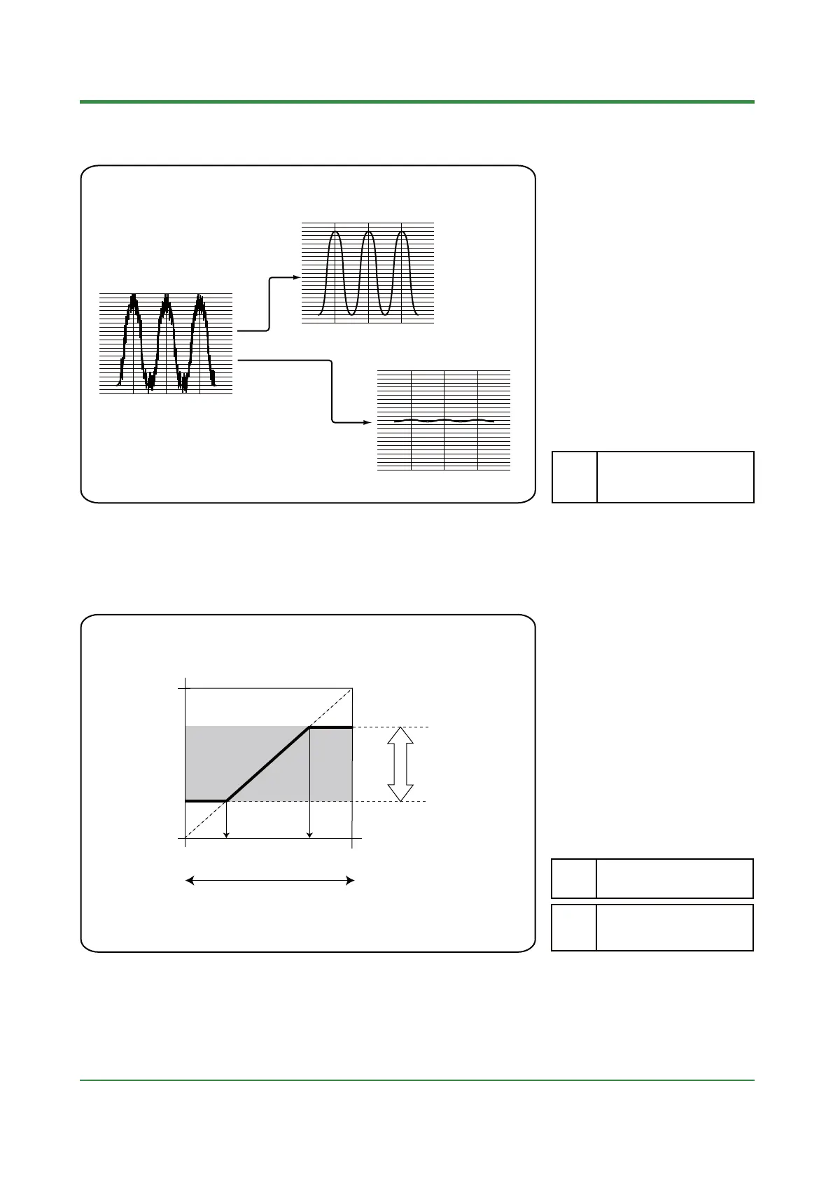
5.3 Reducing Input Variations
•
If input noise or variations cause the
low-order display digits to fluctuate so
that the displayed value is difficult to
read, filtering of inputs will reduce the
variations.
•
Filtering is used by setting a 1st-order
lag time constant; this is set using the
parameter "FL" (PV input filter).
•
Filter Effect
OFF, 1 to120 seconds
FL
Parameter Range
With a small time constant
Actual input
With a large time constant
5.4 Setting Maximum and Minimum Values of Target
Setpoint Range
•
o s
a
ze opera
on or pro
ec
equipment, it may be necessary not to
allow use of the full setpoint operating
range, but rather to some narrower range.
•
In such cases, the minimum value and
maximum value of target setpoint can be
set to restrict the setpoint to the range
between those values.
•
The minimum value and maximum
value of target setpoint are set using the
parameters "SPL" (minimum value of
target setpoint) and "SPH" (maximum
value of target setpoint).
Actual setpoint
PV input range (scale)
Original setting range
Actual setpoint
operating range
800
(°C)
(°C)
0
0
800
200 650
SPL setpoint SPH setpoint
(SPL + 1°C) to
Maximum
value of PV input range
(scale)
SPL
Parameter Range
Minimum value of PV input
range (scale)
to (SPH — 1°C)
SPH
=
 Loading...

