<Toc> <2. Initial Settings>
2-7
IM 05D01D02-41E 4th Edition: May 31, 2006-00
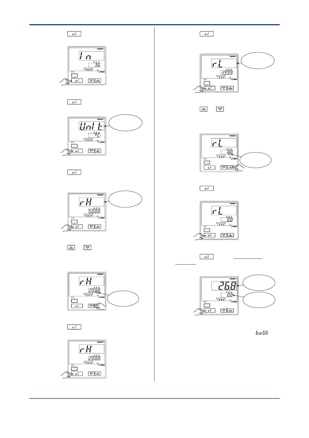
9.
Press the
SET/ENT
key once to register the
setpoint.
PV
MAN
A/M
SP
AL123
SP
234
SET/ENT
10.
Press the
SET/ENT
key once to display the
parameter “UNIT” (PV input unit).
PV
MAN
A/M
SP
AL123
SP
234
SET/ENT
Displays
parameter
“UNIT”.
11.
Press the
SET/ENT
key once to display the
parameter “RH” (maximum value of PV
input range).
PV
MAN
A/M
SP
AL123
SP
234
SET/ENT
Displays
parameter
“RH”.
12.
Press the or key to display the
required setpoint. The figure below shows
an example of setting the maximum value
of PV input range to 200.0C.
PV
MAN
A/M
SP
AL123
SP
234
SET/ENT
Blinks during
change.
13.
Press the
SET/ENT
key once to register the
setpoint.
PV
MAN
A/M
SP
AL123
SP
234
SET/ENT
14.
Press the
SET/ENT
key once to display the
parameter “RL” (minimum value of PV
input range).
PV
MAN
A/M
SP
AL123
SP
234
SET/ENT
Displays
parameter
“RL”.
15.
Press the or key to display the
required setpoint. The figure below
shows an example of setting the mini-
mum value of PV input range to 0.0C.
PV
MAN
A/M
SP
AL123
SP
234
SET/ENT
Blinks during
change.
16.
Press the
SET/ENT
key once to register the
setpoint.
PV
MAN
A/M
SP
AL123
SP
234
SET/ENT
17.
Press the
SET/ENT
key for more than 3
seconds. This returns you to the display
shown at power-on (figure below).
PV
MAN
A/M
SP
AL123
SP
234
SET/ENT
Displays
target setpoint.
Displays PV.
The PV display in the figure above shows
the error code for input burnout ( )
if PV input wiring is not yet complete. The
error code disappears when you wire the
PV input terminals correctly.
Artisan Technology Group - Quality Instrumentation ... Guaranteed | (888) 88-SOURCE | www.artisantg.com

 Loading...


