4-8
<Toc> <4. Troubleshooting and Maintenance>
IM 05D01D02-41E 4th Edition: May 31, 2006-00
4.2.5 Replacing Control Output Relays
This subsection describes how to replace the control output relays.
Since inspection is needed in case parts are replacement will be carried out by a
YOKOGAWA engineer or an engineer certified by YOKOGAWA. When replacement is
required, contact your nearest YOKOGAWA dealer.
CAUTION
Always turn off the power before starting the work in order to avoid electric shock.
Do not pull out the internal unit for any other purpose other than to replace the control
output relays.
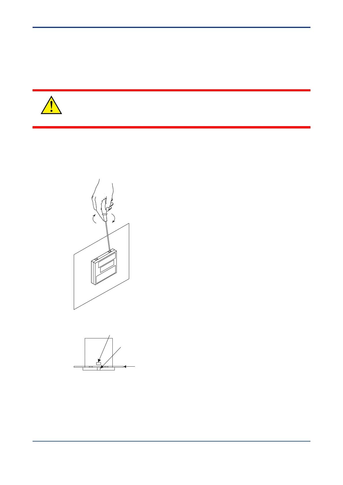
1.
Insert a flat-blade screwdriver (tip width of 6 mm is recommended) into the opening with
the tip in parallel with the front panel, and then turn the screwdriver gently. Take this
procedure to four openings 1, 2, 3 and 4 (see the figure below) on the upper and lower
parts of the bezel, in order.
The bezel slightly moves forward from the housing.
1
2
4
3
2.
Push up the center of the bottom gasket of bezel by a finger to release the latch.
Center of the bottom gasket
Panel
View from the bottom
Latch (invisible in the panel)
3.
Insert the screwdriver into the four openings and flip the tip forward to move the bezel
more forward.
Artisan Technology Group - Quality Instrumentation ... Guaranteed | (888) 88-SOURCE | www.artisantg.com

 Loading...


