7.4.2 Frequency Measurement
Item Specifications
Measured item Voltage and current frequencies applied to the selected input element can be measured.
WT332 (two element model)
Select voltage (U1)/current (I1) of input element 1 or voltage (U3)/current (I3) of input element 3.
WT333 (three element model)
Select voltage (U1)/current (I1) of input element 1, voltage (U2)/current (I2) of input element 2 or
voltage (U3)/current (I3) of input element 3.
Method Reciprocal method
Frequency measuring range
Varies depending on the data update interval (see description given later) as follows:
Data Update Interval
Measurement Range
0.1s 25Hz≤f≤100kHz
0.25s 10Hz≤f≤100kHz
0.5s 5Hz≤f≤100kHz
1s 2.5Hz≤f≤100kHz
2s 1.5Hz≤f≤50kHz
5s 0.5Hz≤f≤20kHz
Only for the direct current input of the WT310HC, the maximum measurement range is 20 kHz.
Measurement range Auto switching among six types: 1 Hz, 10 Hz, 100 Hz, 1 kHz, 10 kHz, and 100 kHz
Frequency filter Select OFF or ON (cutoff frequency at 500 Hz).
Accuracy Requirements
•
When the input signal level is 30% or more of the measurement range if the crest factor is set
to 3 (60% or more if the crest factor is set to 6)
• Frequency filter is ON when measuring voltage or current of 200 Hz or less.
Accuracy: ±(0.06% of reading)
7.4.3 Computation
Item Specifications
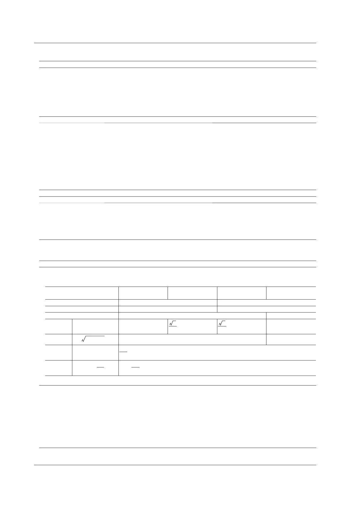
Computingequationofapparentpower(S),reactivepower(Q),powerfactor(λ),andphaseangle(Φ)
i : Input element number
Single-Phase, Three-
Wire (1P3W)
Three-Phase, Three-
Wire (3P3W)
Three-Phase, Three-
Wire (3V3A)
Three-Phase, Four-
Wire (3P4W)
UΣ[V] (U1+U3)/2 (U1+U2+U3)/3
IΣ[A] (I1+I3)/2 (I1+I2+I3)/3
PΣ[W] P1+P3 P1+P2+P3
SΣ[VA] Si=Ui×Ii S1+S3
S1+S2+S3
QΣ[var]
Qi=
Q1+Q3 Q1+Q2+Q3
λΣ λi=Pi/Si
Φ[°]
Φi=
• OntheWT310/WT310HC/WT332/WT333,S,Q,λ,andΦarederivedthroughthecomputationofthemeasuredvaluesof
voltage, current, and active power. Therefore, for distorted signal input, the value obtained on the WT310/WT310HC/WT332/
WT333 may differ from that obtained on other instruments that use a different method.
• If the voltage or current is less than 0.5% (less than or equal to 1% if the crest factor is set to 6) of the rated range, zero is
displayedforSorQ,anderrorisdisplayedforλandΦ.
• For Q[var], when the current leads the voltage, the Q value is displayed as a negative value; when the current lags the voltage,
theQvalueisdisplayedasapositivevalue.ThevalueofQΣmaybenegative,becauseitiscalculatedfromtheQofeach
element with the signs included.
7.4 Features