5-1
IM WT310-02EN
External I/0 (Option)
5.1 External I/O Connector Pin Arrangement and
Pinout
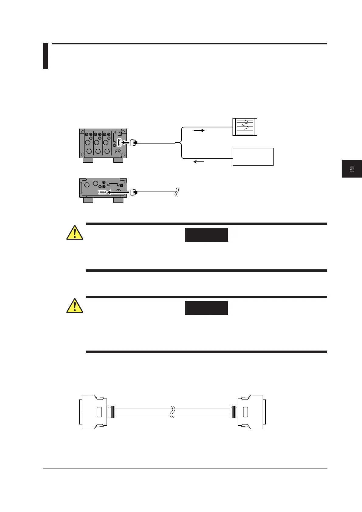
If you select the /DA4 or /DA12 option, D/A output and remote control features are installed in the
WT310/WT310HC/WT330.
You can use the external I/O connector on the rear panel to control the WT310/WT310HC/WT330
remotely and produce D/A output.
WT310/WT310HC
WT330
Remote control
signal source
Recorder
D/A output
Remote signal
Remote Control
CAUTION
Only apply voltages that are within the range of 0 V to 5 V to the remote control input pins.
Do not short or apply external voltages to the output pins. Doing so may damage the WT310/
WT310HC/WT330.
D/A Output
CAUTION
• Do not short or apply an external voltage to the D/A output terminal. Doing so may damage
the WT310/WT310HC/WT330.
• When connecting the D/A output to another device, do not connect the wrong signal pin.
Doing so may damage the WT310/WT310HC/WT330 or the connected instrument.
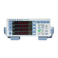
D/A Cable (B9879SX)
Cut the D/A cable to the necessary length, strip the insulation around the internal core wires, and
connect the cable to another device.
Chapter 5 External I/0 (Option)