2-5
IM WT310-02EN
Making Preparations for Measurements
Rack Mounting
To mount the instrument on a rack, use a rack mount kit (sold separately).
• For the WT310/WT310HC
Item Model Note
Rack mount kit 751533-E2 For EIA single mount
Rack mount kit 751533-J2 For JIS single mount
Rack mount kit 751534-E2 For EIA dual mount
Rack mount kit 751534-J2 For JIS dual mount
• For the WT330
Item Model Note
Rack mount kit 751533-E3 For EIA single mount
Rack mount kit 751533-J3 For JIS single mount
Rack mount kit 751534-E3 For EIA dual mount
Rack mount kit 751534-J3 For JIS dual mount
A summary of the procedure for mounting the instrument on a rack is given below. For detailed
instructions, see the manual that is included with the rack mount kit.
1.
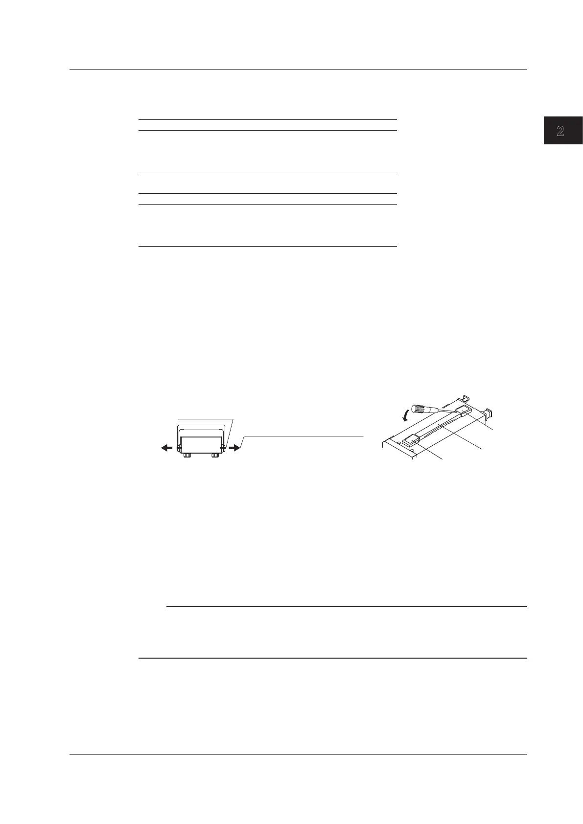
Remove the handle from the instrument.
• WT310/WT310HC
Rotate the handle to position 8 (see the figure on the previous page), and then pull out the rotating base
of the handle by approximately 10 mm on both sides.
• WT330
Remove the handle attachment section cover, and remove the handle attachment screws.
Rotating base
To remove the handle, rotate
the handle to position 8, and
then pull out the rotating base
of the handle by approximately
10 mm on both sides.
WT310/WT310HC WT330
Cover
Cover
Handle
For detailed instructions for the procedures below, see the manual that is included with the rack mount kit.
2.
Remove the feet from the bottom of the instrument.
3.
Peel off the seals over the rack mount attachment holes on both side panels of the instrument,
and pull out the rubber rivets.
4.
Place seals over the feet and handle attachment holes.
5.
Attach the rack mount kit to the instrument.
6.
Mount the instrument on a rack.
Note
• When rack-mounting the instrument, allow at least 20 mm of space around the inlet and exhaust holes to
prevent internal heating.
• Make sure to provide adequate support from the bottom of the instrument. The support should not block the
inlet and vent holes.
2.2 Installing the Instrument