EasyManuals Logo

YOKOGAWA WT310 User Manual

YOKOGAWA WT310
122 pages
To Next Page IconTo Next Page
To Previous Page IconTo Previous Page
Page #67 background imageLoading...
Page #67 background image
2-37
IM WT310-02EN
Making Preparations for Measurements
1
2
3
4
5
6
7
App
Index
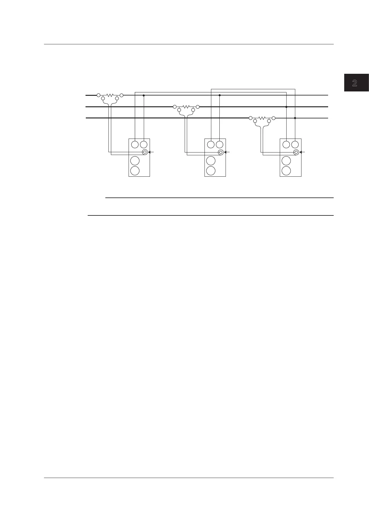
Wiring Example with the Three-Voltage, Three-Current Method
(3V3A) and Shunt-Type Current Sensors
Model: Applies to the WT333.
The wiring is connected to input elements 1, 2, and 3.
SOURCE LOAD
R
S
T
OUT LOUT H
OUT LOUT H
Element 3
Element 1
Element 2
OUT LOUT H
EXT EXT EXT
C
±
±
V
C
±
±
V
C
±
±
V
Note
For details about the relationship between the wiring system and how measured and computed values are
determined, see appendix 1, “Symbols and Determination of Measurement Functions.”
2.10 Wiring the Circuit under Measurement When Using Current Sensors

Table of Contents

Questions and Answers:

Question and Answer IconNeed help?

Do you have a question about the YOKOGAWA WT310 and is the answer not in the manual?

YOKOGAWA WT310 Specifications

General IconGeneral
ModelWT310
CategoryDigital Power Meter
Current Measurement Range0.5 mA to 20 A
WeightApprox. 3.5 kg
Voltage Measurement Range15 V to 600 V
Frequency Range100 kHz
Basic Accuracy0.1%
Power Accuracy0.1%
DisplayLCD
InterfacesUSB, RS-232, GP-IB
Input Elements1
Dimensions213 mm x 88 mm x 346 mm

Related product manuals