EasyManuals Logo

YOKOGAWA WT310 User Manual

YOKOGAWA WT310
122 pages
To Next Page IconTo Next Page
To Previous Page IconTo Previous Page
Page #70 background imageLoading...
Page #70 background image
2-40
IM WT310-02EN
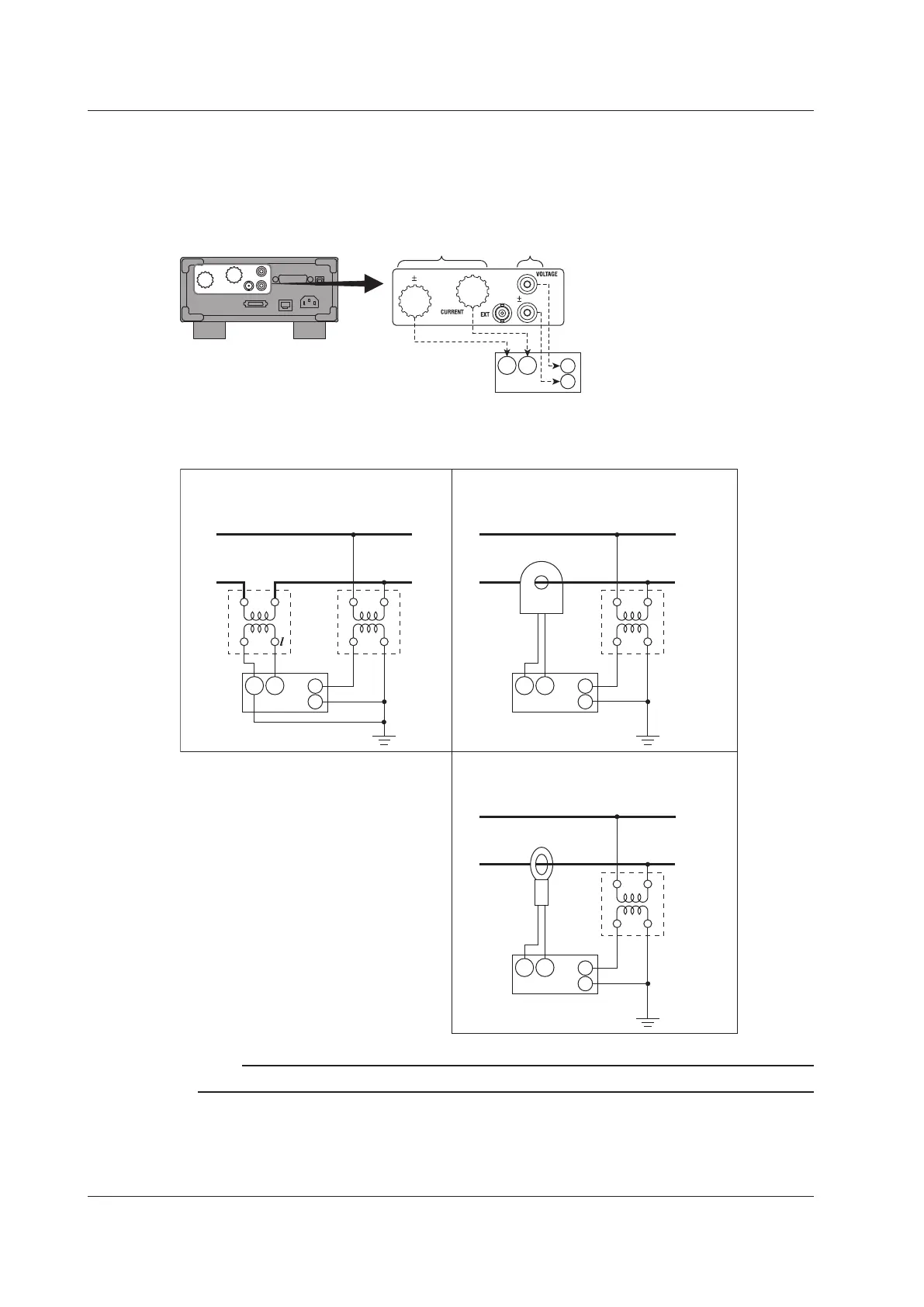
Connecting to the WT310/WT310HC
In the wiring examples that follow, the WT310/WT310HC input elements, voltage input terminals, and
current input terminals are simplified as shown in the following figure.
WT310/WT310HC
Input element
C
±
V
±
Voltage input
terminals
Current input
terminals
Wiring Example
The following figures show how to connect to the WT310/WT310HC.
SOURCE LOAD
L
CT
VT
V
v
SOURCE LOAD
VT
V
v
C
±
V
±
Pass-through CT
C
±
V
±
VT and pass-through CTVT and CT
SOURCE LOAD
VT
V
v
C
±
V
±
Clamp-type current
sensor that outputs
current
VT and Clamp-type Current Sensor
That Outputs Current
Note
Some CTs (including through types) require load resistance and power supplies. Check your CT’s manual.
2.11 Wiring the Circuit under Measurement When Using a Voltage or Current Transformer

Table of Contents

Questions and Answers:

Question and Answer IconNeed help?

Do you have a question about the YOKOGAWA WT310 and is the answer not in the manual?

YOKOGAWA WT310 Specifications

General IconGeneral
ModelWT310
CategoryDigital Power Meter
Current Measurement Range0.5 mA to 20 A
WeightApprox. 3.5 kg
Voltage Measurement Range15 V to 600 V
Frequency Range100 kHz
Basic Accuracy0.1%
Power Accuracy0.1%
DisplayLCD
InterfacesUSB, RS-232, GP-IB
Input Elements1
Dimensions213 mm x 88 mm x 346 mm

Related product manuals