EasyManuals Logo

YOKOGAWA WT310 User Manual

YOKOGAWA WT310
122 pages
To Next Page IconTo Next Page
To Previous Page IconTo Previous Page
Page #71 background imageLoading...
Page #71 background image
2-41
IM WT310-02EN
Making Preparations for Measurements
1
2
3
4
5
6
7
App
Index
Connecting to the WT330
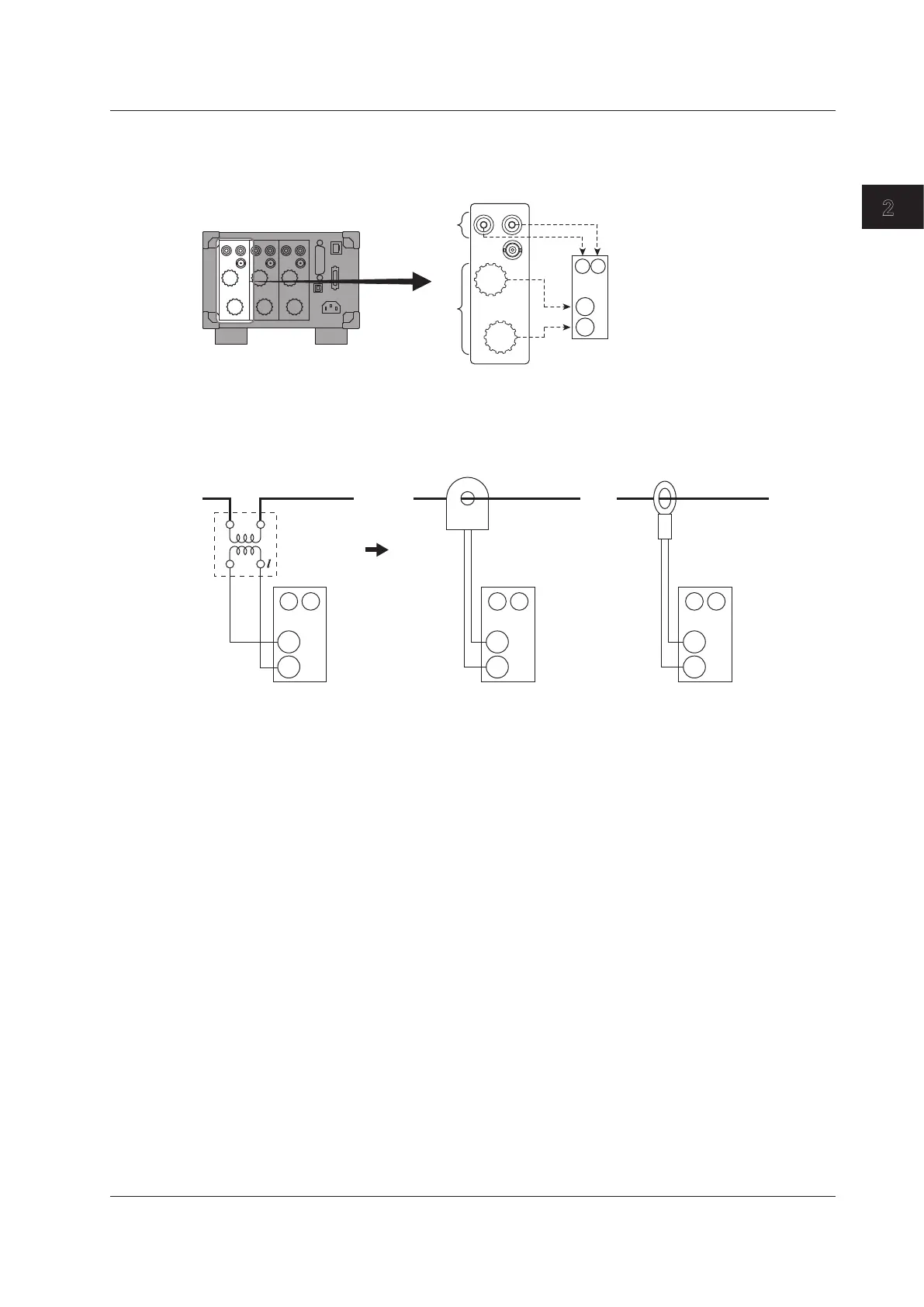
In the wiring examples that follow, the WT330 input elements, voltage input terminals, and current
input terminals are simplified as shown in the following figure.
VOLTAGE
±
±
CURRENT
EXT
Input element
C
±
V
±
Voltage input
terminals
Current input
terminals
WT330
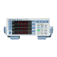
Also, the wiring examples are for when a CT is connected. When connecting a pass-through CT or a
clamp-type current sensor that outputs current, substitute the CT with the pass-through CT or clamp-
type current sensor.
Clamp-type current
sensor that outputs
current
C
±
±
V
L
CT
C
±
±
V
Input element Input element
Pass-through CT
C
±
±
V
Input element
2.11 Wiring the Circuit under Measurement When Using a Voltage or Current Transformer

Table of Contents

Questions and Answers:

Question and Answer IconNeed help?

Do you have a question about the YOKOGAWA WT310 and is the answer not in the manual?

YOKOGAWA WT310 Specifications

General IconGeneral
ModelWT310
CategoryDigital Power Meter
Current Measurement Range0.5 mA to 20 A
WeightApprox. 3.5 kg
Voltage Measurement Range15 V to 600 V
Frequency Range100 kHz
Basic Accuracy0.1%
Power Accuracy0.1%
DisplayLCD
InterfacesUSB, RS-232, GP-IB
Input Elements1
Dimensions213 mm x 88 mm x 346 mm

Related product manuals