Default Values for Integration: dFLt-i
Select this setting to output integrated values. The output settings are as follows:
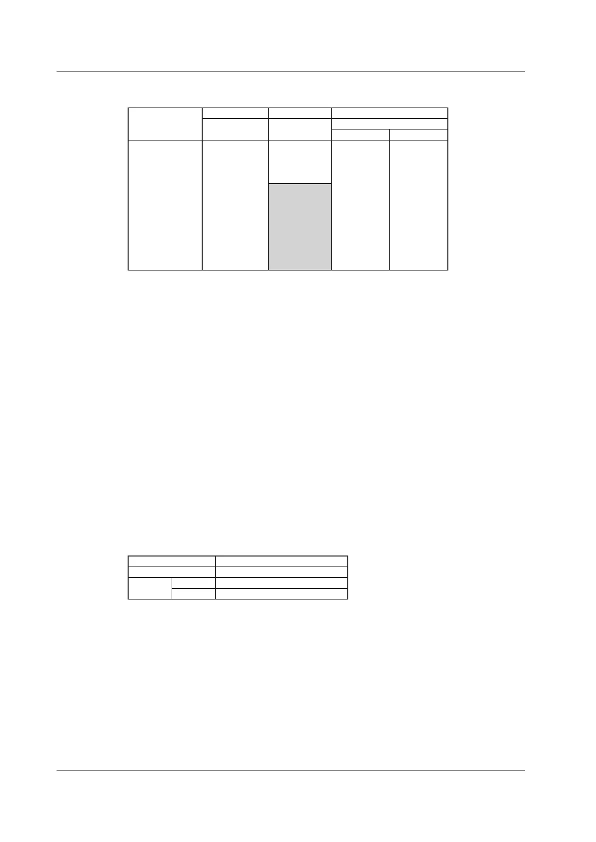
Suffix Code /DA4 /DA12
Product Name WT310
WT310HC
WT330
WT332 WT333
Output Channel ch1 P1 P1 P1
ch2 WP1 - P2
ch3 q1 P3 P3
ch4 fU PΣ PΣ
ch5
1
WP1 WP1
ch6 - WP2
ch7 WP3 WP3
ch8 WPΣ WPΣ
ch9 q1 q1
ch10 - q2
ch11 q3 q3
ch12 qΣ qΣ
1
These channels cannot be set.
2 The numbers are used to indicate input elements 1, 2, and 3.
Configuring an Original Output Format
You can specify output items (output functions and elements) for each output channel.
Output Functions (Area A in step 8 in the procedural explanation
for setting the D/A output format)
You can select from the following options.
u (voltage U), i (current I), P (active power P), VA (apparent power S),
VAr(reactivepowerQ),PF(powerfactorλ),dEG(phaseangleΦ),
uFrq (voltage frequency fU), iFrq (current frequency fI),
uP (peak voltage value Upk), iP (peak current value Ipk),
Ph (sum of watt hours Wp), Ph+ (positive watt hour Wp+), Ph– (negative watt hour Wp–),
Ah (sum of ampere hours q), Ah+ (positive ampere hour* q+), Ah– (negative ampere hour* q-),
MATH (integration), ---- (0 V D/A output; no element is specified)
* For more information about positive and negative ampere hours, see page 5-4 of the User’s
Manual, IM WT310-01EN.
Elements (Area B in step 10 in the procedural explanation for setting the D/A output
format)
Product Name Element
WT310 or WT310HC 1
WT330 WT332 1, 3, or 4
WT333 1, 2, 3, or 4
Elementnumber4representsΣ.
5.3 Producing D/A Output