<10. Other Functions>
10-38
IM 11M12G01-02EN 1sh Edition : Mar. 25, 2021-00
(1) (2)
Figure 10.32 Flow of span gas (air)
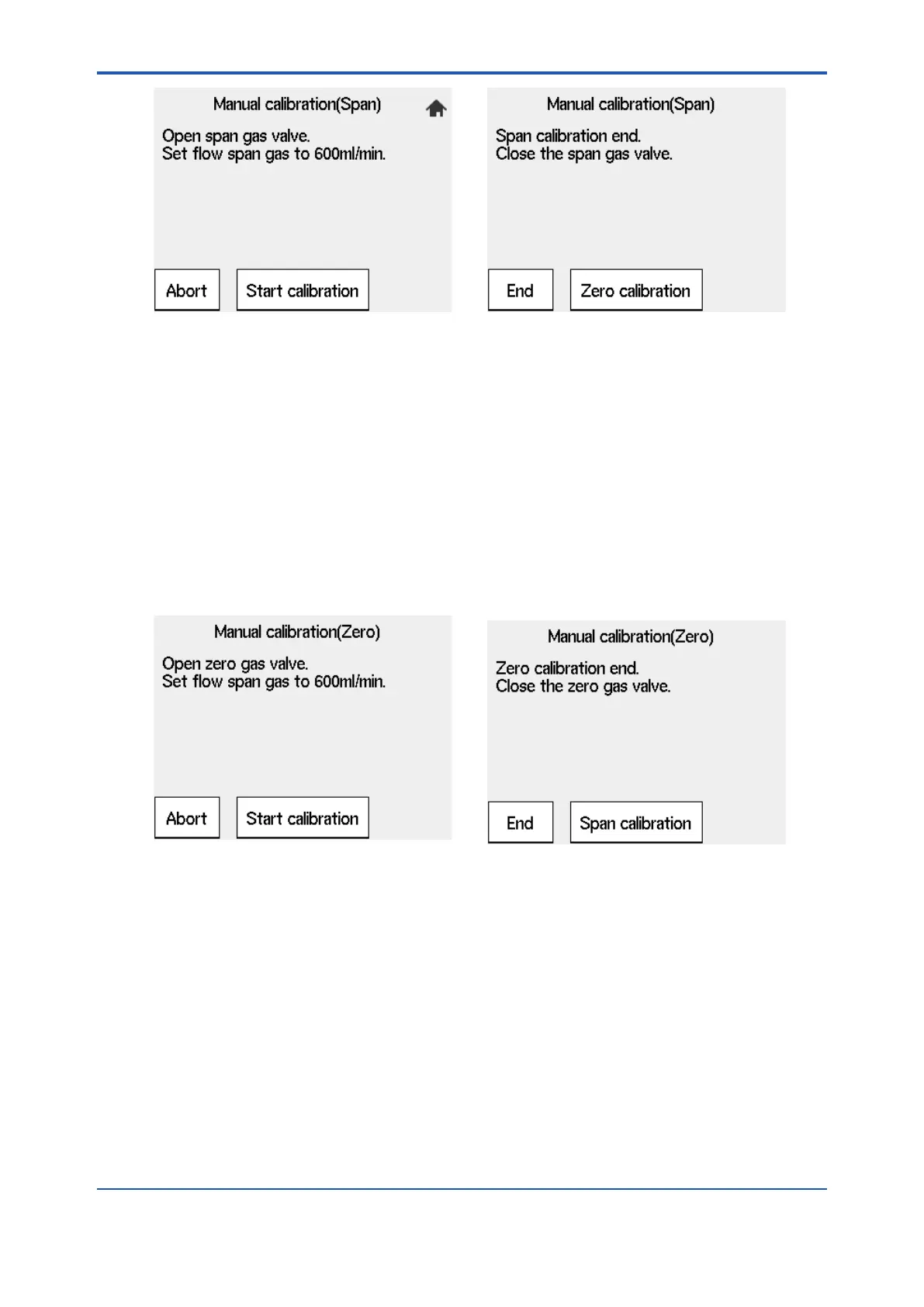
(4) Select “Valve opened” (to start calibration) from the Manual calibration display shown in
Figure 10.15. Check the Trend graph display to see that the measured value is stabilized.
Then press the [Enter] key. The Manual calibration display shown in Figure 10.16 appears.
Disconnect the power cord to stop the pump.
<Flow of zero gas>
Feeds zero gas by following the instruction on the converter.
Figure 10.33 Flow of zero gas
(1) Use the needle of the zero gas valve “ CHECK GAS “ to puncture a hole in the gas cylinder
installed as described in Section “10.11.2 Installing Gas Cylinders”. Fully clockwise turn
the valve regulator by hand.
line when the valve is slowly opened). Turn the regulator of the zero gas valves back slowly
greatly, readjust the valve.
(3) Select “Valve opened” (to start calibration) from the Manual calibration display. Check the
Trend graph display to see that the measured value is stabilized. Then press the [Enter] key.
immediately. Turn the zero gas valve regulator fully clockwise. If this valve regulator is not
properly adjusted, the needle valve will not close completely and a cylinder gas may leak.
 Loading...


